So here you saw Circuit Diagram Of DC Shunt Motor. The dc shunt motor circuit diagram is shown below and the flow of current and voltage subconscious supplied to the motor from the supply can be given by itotal e dc shunt motor circuit diagram in prosecution of the shunt wound dc motor this current supply will divide into two ways past ia ish where ia will supply throughout the ra.
Shunt Wound Dc Motor Wiring Diagram Diagram Wire Motor
A DC shunt motor also known as a shunt wound DC motor is a type of self-excited DC motor where the field windings are shunted to or are connected in parallel to the armature winding of the motor.

Shunt Wound Dc Motor Wiring Diagram. The armature circuit and the shunt field circuit are connected across a DC source of fixed voltage Vt. October 8 2020 by masuzi. These can be used as part of either an instructor-led course or self-directed study.
It shows the components of the circuit as simplified shapes and the facility and signal contacts together with the devices. It shows the components of the circuit as simplified. A1.
The shunt winding is made up of many. Motor Wiring Diagram DC. A shunt-wound DC generator.
If either the leads of the field windings or the rotor windings are swapped this can cause the motor to reverse rotation direction. DC Shunt Motor Circuit Diagram. The Shunt Wound DC Motor Training Systems courseware consists of a textbook on motors and motor control instructor and student wiring diagrams and a users guide with hands-on exercises.
A DC shunt motor also known as a shunt wound DC motor is a type of self-excited DC motor where the field windings are shunted to or are connected in parallel to the armature winding of the motor. Motor wiring diagram d c. Types Of Dc Motors And Their Applications Electrical4u.
A wiring diagram usually gives opinion virtually the relative outlook and contract of. In a DC Shunt motor the field winding is connected in parallel shunt with the armature. Shunt Wound Motors Four Wire Type Connect the motor armature as described in Section IIC on page 10.
The output voltage of a shunt-wound generator may be controlled by means of a rheostat connected in series with the shunt field. However if the load fluctuates the voltage also varies. The DC shunt motor circuit diagram is shown below and the flow of current and voltage being supplied to the motor from the supply can be given by Itotal E.
The shunt winding is wound from many turns of small copper wire and since it is connected across the DC field supply its field current will be constant. Dc shunt motor construction circuit types of dc motor shunt series diagram of the dc shunt motor types of dc motor shunt series. Shunt wound dc motor wiring diagram.
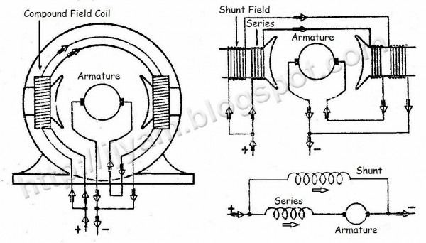
The electrical cable that is admired by the whole world. A compound wound DC motor also known as a DC compound motor is a type of self-excited motor and is made up of both series the field coils S 1 S 2 and shunt field coils F 1 F 2 connected to the armature winding as shown in the figure below. Dc Compound Motor Everything You Need To Know About It Tutorial.
Shunt Wound Dc Motor Wiring Diagram wiring diagram is a simplified standard pictorial representation of an electrical circuit. Hope you liked this diagram. A DC Motor having both shunt and series field windings is called a Compound Motor.
E1. The working principle of a dc shunt motor is whenever a dc motor is turned on then dc flows throughout stator as well as the rotor. This video will walk you through the connections for a Shunt DC Motor and demonstrate how it runs without a physical load connected to the shaft of the motor.
Compound Wound Motor. How To Control Dc Motors With An Arduino And A Tip120 Darlington Transistor Circuit Basics. Use figure 2 if your motor has a dual voltage shunt field.
In case of the shunt wound DC motor this current supply will divide into two ways like Ia Ish where Ia will supply throughout the Ra. All About Shunt Dc Motors What They Are And How Work. By Margaret Byrd September 2 2017.
The motor takes power from the DC source and therefore. Shunt wound dc motor wiring diagram. Please share this with your friends too.
Easy Concepts Of Shunt Wound Dc Motors Must Watch Concept Motor Wind. This photograph types of dc motor shunt series amp. Shunt Wound Dc Motor Wiring Diagram wiring diagram is a simplified standard pictorial representation of an electrical circuit.
In a cumulative compound motor the flux produced by both. This is opposite to shunt DC motors which wire their field windings in parallel with the armature which produces different effects for a full explanation take a look at our article all about shunt DC motors. Compound Wound Dc Motor Or Electrical4u.
A shunt-wound motor has decreasing torque as speed increases. Since they are connected in parallel the armature and field windings are exposed to the same supply voltageThough there are separate branches for the. Wound dc motor or series types of shunt circuit diagram 4 motors and their wiring dpdt reversing switch how to use in arduino sd controller circuits connections for nema 6 wire 8 stepper brushless vs brushed when compound tutorial calculations theory worksheet electric.
Types Of Dc Motor Shunt Series Compound Wound Circuit Globe. The compound motor is further subdivided as Cumulative Compound Motor and Differential Compound Motor. A Circuit Diagram Of Separately Excited Shunt Wound Dc Traction Scientific.
Use figure 1 if your motor has a single voltage shunt field. Compound wound dc motor or electrical4u calculations electric motors types of shunt series circuit globe the engineering knowledge steadt state equivalent moving coil and diagram characteristics applications characteristic ulative my tech info everything you need to know about it tutorial alone mulative short suitable for high starting torque its selection 4 their. Both the field coils provide for the required amount of magnetic flux that links with the armature coil and brings about the.
B Wiring Diagram c Schematic Diagram A shunt-wound generator is suitable if the load is constant. The connection diagram of the compound motor is shown below. Connect full voltage field wires 90 Volt DC motors with 100 Volt DC field and 180 Volt DC motors with 200 Volt DC field to F and F- terminals of Terminal Block TB2 as described in Section IID on page 10.
Lets understand the meaning of the letters marked in this diagram. As these two parts are connected in parallel the armature and field windings are exposed to the same supply voltage. Dc Shunt Motor Construction Circuit Diagram And Its Applications.
Shunt Wound Dc Motor Wiring Diagram. Shunt Dc Motor Schematic Diagram. Dc Motor Types Shunt Series Compound Permanent Magnet Electrical A2z.
These connections are in accordance with NEMA MG-1 and American Standards Publication 06. An external field rheostat Rfc is used in the field circuit to control the speed of the motor. Sd Control Of Dc Motor Shunt Series Electrical4u.
A schematic diagram of a shunt field DC motor is shown in Fig330. Shunt field dc motor connection the method of connection for a shunt field direct current motor is shown in figure 2 below. A shunt motor known as a shunt wound DC motor is a type of DC motor which is self-excited and has the field windings that are connected in parallel to the armature winding of the motor.
Motor Connections Your motor will be internally connected according to one of the diagrams shown below.

Wiring Diagram For Shunt Trip Breaker Diagram Breakers Trip

Ac Wiring Diagram Of Window Airconditioner Ac Wiring Thermostat Wiring Electrical Wiring Diagram

Weg Motor Capacitor Wiring Diagrams Schematics And Baldor Diagram In Electric Motor Electrical Wiring Diagram Motor

60 Beautiful Motor Starter Wiring Diagram Electrical Circuit Diagram Circuit Diagram Electrical Wiring Diagram

Unique Wiring Diagram Ac Blower Motor Diagram Diagramtemplate Diagramsample Thermostat Wiring Ac Wiring Electrical Wiring Diagram

Motor Forward Reverse Wiring Diagram Elec Eng World Electrical Wiring Diagram Electrical Circuit Diagram Basic Electrical Wiring

Unique Single Phase Capacitor Start Capacitor Run Motor Wiring Diagram Electrical Wiring Diagram Electrical Circuit Diagram Capacitor
Dual Cooling Fan Wiring Diagram Electric Cooling Fan Radiator Fan Automotive Electrical

Capacitors For Compressor Wiring Diagram Ac Capacitor Capacitor Compressor

Single Phase Motor With Capacitor Forward And Reverse Wiring Diagram Circuit Diagram Electrical Circuit Diagram Electrical Diagram

Domestic Refrigerator Wiring Electrical Wiring Diagram Circuit Diagram Refrigeration And Air Conditioning

45 Unique Reversing Motor Starter Wiring Diagram Electrical Circuit Diagram Circuit Diagram Electrical Symbols

Bodine Electric Motor Wiring Electric Motor Types Of Electrical Wiring Electrical Circuit Diagram

Wiring Diagram Ac Generator Valid Modern Dc Wiring Gallery Circuit Diagram Electrical Circuit Diagram Diagram

Baldor Motor Wiring Diagrams Single Phase Electrical Wiring Diagram Electrical Diagram Electrical Circuit Diagram

Awesome Three Wire Alternator Wiring Diagram Gm Diagrams Digramssample Diagramimages Wiringdiagramsample W Alternator Electrical Diagram Voltage Regulator

Air Conditioner C S R Wiring Diagram Compressor Start Full Wiring Fully4 Air Conditioner Maintenance Refrigeration And Air Conditioning Hvac Air Conditioning

10 General Electric Furnace Wiring Diagram Electrical Diagram Washing Machine Motor Types Of Electrical Wiring

Wiring Diagram For 220 Volt Single Phase Motor Http Bookingritzcarlton Info Wiring Diagram For 2 Electrical Diagram Electrical Wiring Diagram Electric Motor