In this article were going to show you how to wire a few different pressure transducer and transmitter. A transducer produces millivolts amplified voltage or current output.
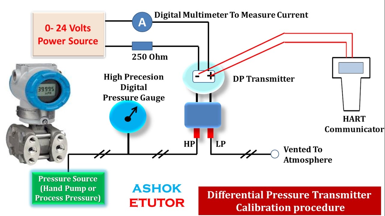
Calibration Procedure Of Differential Pressure Transmitter By Using Hart Transmitter Digital Pressure Gauge Electronic Engineering
These connection methods are of great concern to the instrument engineertechnician.

2 Wire Pressure Transmitter Wiring Diagram. A 4-wire transmitter has 2 wires connected to a power supply and 2 signal wires connected to the PLC. A 2-wire transmitter has only 2 wires and is connected in series with the power supply and the PLC. Common Troubleshooting for 2-wire 4-20ma Pressure Transmitter Date.
A first look at a circuit diagram could possibly be confusing but if read a subway map read schematics. It is possible to convey electrical power and communicate analog information over the same two wires using 4 to 20 milliamps DC if we design the transmitter to be loop-powered. Pressure Transmitter With Current Output 2-Wire Technical data Type PT300PSIG-13-LI3-H1131 Ident.
The diagram below below shows a simple wiring configuration for current loop pressure transmitter. 2 wire transmitter wiring diagram. 44 mm 4 150-in.
Wika A-10 Wiring Diagram Ub. Transmitter with traditional flange and optional flange adapters. 2-wire loop-powered transmitter current loops.
Pressure Transducer and Transmitter Wiring Explained Learn how to wire different transducers and transmitters to digital and analog PLC input modules. Either the transmitter or the receiver would provide the power supply to the loop. Install field wiring conduit into the open transmitter conduit entry for remote mounting and feed wires into the transmitter housing.
2 wire pressure transmitter wiring diagram. In this video we show you how to wire a pressure transducer two ways. Assortment of 2 wire pressure transducer wiring diagram.
The figure above shows the wiring diagram of the two-wire transmitter. The wiring diagram is located inside the housing cover. Typical wiring configurations are shown in Figure 2.
It features a very good accuracy a robust design and an exceptional number of variants meaning it can be suited to the widest. A loop powered transmitter connects to a process controller with only two wires which is why loop-powered transmitters are synonymously. Two wire transducer as shown in the above the power supply is 24 VDC output signal for the DC4-20 ma the load resistance is 250 Ω lowest negative line voltage of 24 v power supply it is the public line signal.
A Beginners Guide to Circuit Diagrams. 2 wire 4-20ma pressure transmitter wiring configuration. In two-wire 4-20mA control loops we use 2-wire transmitters to convert various process signals representing flow speed position level temperature pressure strain pH etc to 4-20mA DC for the purpose of transmitting the signal over some distance with little or no loss of signal.
Wiring Diagram Pics Detail. Here are the most common faults and solutions for 2-wire 4-20ma Pressure Transmitter. Wiring Schematic 2 Cable Wiring Standard Conduit w Cable 3 Submersible Cable Wire 4 Connector Wiring DIN Form A Form C 5 Bendix 6 Pin 4 Pin 6 Packard Metri-Pack 150 7 Minifast and M12x1 8 DT04 DEUTSCH 6 Pin 4 Pin 9 Molex 10 Pressure Temperature Transmitter Wiring Cable or Wire Pressure Temp 11.
A 4 175-in. 44 mm 4 225-in. A pair of 4011 NAND gate stages U1c and U1d are configured like a radio-frequency RF oscillator carrier.
57 mm C 4 175-in. Sig output signal positive UB power supply positive 0V power supply negative Sig – output signal negative. 44 mm D 4 175-in.
This is one of the simplest wiring types as it only has two wires. It is assumed that the measurement device includes a sufficient load resistance for measuring a current loop. Next is a resonance stage and the final stage built with a minimum 1W transistor which must have a heatsink.
All connectors with The model S pressure transmitter for general industrial applications is the ideal solution for customers with demanding measuring requirements. In this configuration supply power and 4-20 mA signal uses two-wire loop connections. Process connection G ¼ A DIN E ¼ NPT and others.
8 August 2020 The two-wire 4-20mA pressure transmitters are widely used in industrial applications like water tanks oil pipelines hydraulic and HVAC etc. 6831461 Pressure range Relative pressure 02068 bar rel. A transmitter produces current output only.
2 wire for current transducers and 3 wire for voltage transducersTo learn more visit. A 4 wire transmitter has 2 wires connected to a power supply and 2 signal wires connected to the plc. These connection methods are of great concern to the instrument engineer technician.
The actual wiring between the transmitter and the power supply depends upon whether it is a 2-wire or a 4-wire type. Brown green brown green white. Attach the sensor leads to the transmitter sensor terminals.
Transmitter with coplanar flange B. Again due to the built-in signal conditioning the transmitters are higher cost and larger in size than the millivolt output transducers. Transmitter with coplanar flange and optional flange adapters C.
Pressure Transmitter Calibration Transmitter Analog Circuits How To Apply Today s electronic process transmitters pressure temperature flow and level are connected in different wire types or configurations. However a separate power supply is also available as an option. Todays electronic process transmitters – pressure temperature flow and level are connected in different wire types or configurations.
1Forpower supplyuseacircuitwithenergylimitation ENULIEC. The 2 – Wire 3 – Wire and 4 – Wire types are often used to describe the method of connection of electronic transmitters. Cable with 5 foot 15m of cable and free ends Circular connector M 12×1 5 pin.
It reveals the parts of the circuit as streamlined shapes and the power as well as signal connections in between the gadgets. Pull the field wiring leads into the terminal side of the housing. The pressure transmitter model A offers excellent quality at an extremely x 1 cable outlet 2 m.
38 mm B 4 288-in. 0300 psi 0207 MPa Admissible overpressure 5171 bar Burst pressure 5171 bar Response time. 2 wire pressure transducer wiring diagram Figure.
Pressure Transducer and Transmitter Wiring Explained. If the measurement device is a multi-meter it is unlikely to include sufficient. The actual wiring between the transmitter and the power supply depends upon whether it is a 2-wire or a 4-wire type.
A 2 wire transmitter has only 2 wires and is connected in series with the power supply and the plc.

Foundation Fieldbus Ff Segment Topology Segmentation Topology Mathematics Geometry

Pin On Jarry

2000 Jetta Radio Wiring Diagram 2001 Volkswagen Car Throughout Fine Car Stereo Car Audio Systems Vw Jetta

Troubleshooting Fieldbus Devices Control Systems Engineering Electrical Wiring Diagram Mathematics Geometry

Wiring Diagram Wireless Transmitter 4 Channel Transmitter
Nu9n Transmitter Essb Ssb Hi Fi Mid Fi Lo Fi Audio Processing Electronic Circuit Projects Electrical Circuit Diagram Transmitter

What Is The Difference Between Pnp And Npn Learn Robotics Learn Robotics Ladder Logic Electrical Wiring Colours

Field Instruments Junction Box Animation Junction Boxes Electronic Schematics Electrical Wiring Diagram

Es200 Wiring Diagram Connection Scheme Automatic Sliding Doors Exterior Patio Doors Diagram

Troubleshooting Fieldbus Devices Control Systems Engineering Electrical Wiring Diagram Mathematics Geometry

Pin On Instrument Klibrasi

Wiring Diagram For Rosemount 3051smv Converted Into Foundation Fieldbus Signal Control Systems Engineering Process Control Analog To Digital Converter

Es200 Wiring Diagram Connection Scheme Diagram Automatic Sliding Doors Automatic Door

Car Trailer Mod Trailer Wiring Diagram Car Camper Trailers

Plc Analog Signals Wiring Methods Analog Signal Ladder Logic Electronic Engineering

Wiring Diagram Of The Distribution Board Mechanical Engineering Technology Distribution Board Engineering Technology

Calibration Procedure Of Differential Pressure Transmitter By Using Hart Communicator In Hindi Youtube Transmitter Digital Pressure Gauge Pressure

Es200 Wiring Diagram Connection Scheme Automatic Sliding Doors Diagram Exterior Patio Doors

Es200 Wiring Diagram Connection Scheme Automatic Sliding Doors Air Conditioning Maintenance Diagram