Leviton 20 Amp Self Test Smartlockpro Slim Duplex Gfci Outlet White R12 Gfnt2 0rw The. Gfci Outlet With Switch Wiring Diagram Every electric structure is made up of various unique pieces.
My Wife And I Just Bought Our First House And Needed To Replace Many Of The Receptacles As They Are Loose And Most Are Gfci Light Switch Wiring Outlet Wiring
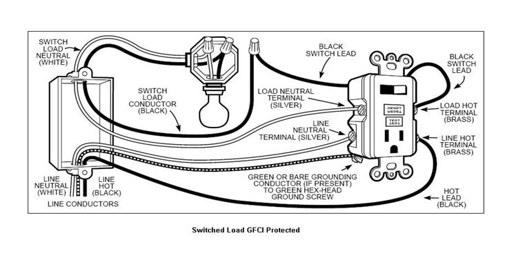
Connect switch leads to control LOAD WITH GFCI PROTECTION – One black switch lead connects to the LOAD HOT.

Gfci Wiring Diagram With Switch. Plug a clock radio or light into the outlet. If there is only 1 cable containing 2-3 wires connect the white line wire to the silver or white terminal and connect the black wire to the brass terminal which is the. Gfci Outlet with Switch Wiring Diagram Sample Wiring Diagram 4.
It includes directions and diagrams for various kinds of wiring methods along with other items like lights home windows etc. Wiring Diagram contains several comprehensive illustrations that present the relationship of varied items. Gfci outlet wiring diagrams do it a with multiple outlets light switch off and connection combo tutorial wire can t reset ground fault circuit interrupter diagram for 20a gfi tamper resistant leviton 20 amp self test smartlockpro 3 way protection installation tips how to.
If applicable – Remove the YELLOW sticker to reveal the LOAD terminals. There are three wires present one red wire attached to the left side upper terminal and two white wires attached to the right side terminals. It means all the connected loads to the load terminals of GFCI are protected.
Gfci Switch Schematic Combo Wiring Wiring Diagram Gfci Outlet With Switch Wiring Diagram. This diagram illustrates the wiring for a circuit with 2 gfci receptacles followed by a light and switch. If there is only 1 cable containing 2-3 wires connect the white line wire to the silver or white terminal and connect the black wire to the brass terminal which is the.
Wiring a GFCI Outlet with Combo Switch Outlet Receptacle Light Switch. Thanks for your electrical question Douglas. Gfci wiring diagram with switch.
In this GFCI outlet wiring and installation diagram the combo switch outlet SPST single way switch and ordinary outlet is connected to the load side of GFCI. If not the structure will not work as it ought to be. This diagram illustrates wiring a GFCI receptacle and light switch in the same outlet box a common arrangement in a bathroom with limited space.
Gfci switch outlet wiring diagrams do it yourself help com leviton gfi combo doityourself community forums 15 amp 125 volt self test tamper resistant and 20 pack white vw2 gfsw1 hw2 the electrical technology combination tutorials https www electricaltechnology org 2020 04 wire html facebook decora. Should you install it. Can I Wire My Gfci Outlets In Series With Another Docking Drawer.
Just click the Wiring Diagrams and GFCI Outlet Wiring link below. Wiring gfci outlet switch combo – Diagram Schematic. By connecting the switch to the load terminals on the last gfci the switch and light are protected against ground faults as well.
Leviton 15 amp 125 volt combo self test gfci switch outlet wiring diagrams do legrand radiant tamper resistant gfsw1 kw tr smartlockpro combination electrical technology eaton gfi switches and receptacles ge wall 59797 com a 2 gang cover wire html 3 way commercial duplex white. Electrical Wiring Diagrams Light Switch Outlet New Erd Diagram. Electrical gfci outlet wiring diagram diagrams do it for multiple receptacle and connection a light switch off with outlets how to install dengarden circuit from wire breaker 20a gfi ground fault interrupter adding after gcfi ge 15 amp self test white protection installation tips testing leviton can t reset anko.
Single-Pole 20-Amp and Single-Pole 30-Amp as well as a 20-Amp GFCI duplex receptacle. Please download these gfci outlet with switch wiring diagram by using the download button or right click selected image then use Save Image menu. It includes directions and diagrams for various kinds of wiring methods along with other items like lights home windows etc.
Identifying the Wiring for a New GFCI Outlet Electrical Question. The existing outlet is controlled by a switch. It is intended to help each of the typical user in building a correct system.
This gfci wiring method may be found in a bathroom or kitchen where the switch may be near a water source. Each component ought to be set and linked to other parts in specific way. Leviton Gfci Wiring Diagram Fresh Wiring Diagram for Gfci Receptacle.
The installation process of this safety switch is a breeze. March 2 2020 by faceitsalon. Installing a GFCI receptacle can be more complicated than installing a conventional receptacle.
Understand basic wiring principles and techniques Can interpret wiring diagrams Have circuit wiring experience Are prepared to take a few minutes. Wiring diagram for gfci and light switch wiring diagram is a simplified up to standard pictorial representation of an electrical circuit it shows the components of the circuit as simplified shapes and the capacity and signal friends in the midst of the devices. 50 amp square d gfci breaker wiring diagram a beginner s guide to circuit diagrams.
The combination GFCISwitchs features 3. Connect the LOAD Receptacle cable wires to the GFCI LOAD terminals. – The white wire connects to the WHITE terminal Silver.
There are three wires present one red wire attached to the left side upper terminal and two white wires attached to the right side terminals. Gfci Receptacle With A Light Fixture With An Onoff Switch In Wiring A Gfci Outlet With A Light Switch Diagram. Direct main power supply.
I am replacing an ungrounded 2nd generation duplex outlet with a GFCI outlet. Connect the earthing or grounding wire to the downside terminal of the outlet as shown in the above wiring diagram. Wiring Diagram contains several comprehensive illustrations that present the relationship of varied items.
Assortment of gfci outlet with switch wiring diagram. How Do I Wire 3 Way Gfci Combo Switch Outlet X Leviton Online Knowledgebase. The existing outlet is controlled by a switch.
Collection of gfci outlet with switch wiring diagram youll be able to download totally free. Wiring Diagram arrives with a number of easy to follow Wiring Diagram Directions. Gfci outlet with switch wiring diagram How to Install A Gfci with 4 Wires Luxury Wiring Diagrams for A Gfci Outlet Do.
In the second wiring diagram the lamp is connected directly to the line terminals of GFCI ie. These directions will probably be easy to comprehend and use. To be able to make sure the electric circuit is built properly Gfci Outlet With Switch Wiring Diagram is needed.
– The black wire connects to the HOT terminal Brass. Gfci Outlet with Switch Wiring Diagram Sample. Make sure that you.
Gfci Switch Schematic Combo Wiring Wiring Diagram Gfci Outlet With Switch Wiring Diagram. Turn the power OFF and check the wire connections against the appropriate wiring diagram in step 7A or 7B. This diagram illustrates the wiring for a circuit with 2 gfci receptacles followed by a light and switch.
The source hot wire is spliced with one of the switch wires and the other switch wire is connected to the hot LINE terminal on the device. LOAD A cable consists of 2 or 3 wires. This diagram illustrates the wiring for a circuit with 2 gfci receptacles followed by a light and switch.
The wires attaching to the gfi outlet connect to the line side. There are fully explained wiring instructions complete with a picture series of several GFCI installations and GFCI wiring diagrams which can be found here in the GFCI and Light Switch area here in this website. In the first wiring diagram the connected load as light bulb is GFCI protected as it is control by the combo switch and connected to the load terminals of GFCI.

Wiring Diagram For A Gfci Outlet And Light Switch In The Same Box Outlet Wiring Electrical Wiring Light Switch Wiring

How To Install And Troubleshoot Gfci Home Electrical Wiring Wire Switch Outlet Wiring

Image Result For Wiring Outlets And Lights On Same Circuit Electrical Wiring Home Electrical Wiring Gfci Wiring Diagram

How To Wire Gfci Combo Switch Http Waterheatertimer Org How To Wire Gfci Html Gfci Combo Wire Switch Gfci Light Switch Wiring

Gfci Outlet Wiring Diagram Electrical Wiring Diagram Outlet Wiring Home Electrical Wiring

Gfic Protected Switch Outlet Wiring Gfci Home Electrical Wiring
Wiring Diagram For A Gfci Outlet And Light Switch In The Same Box Outlet Wiring Electrical Wiring Light Switch Wiring

Multiple Gfci Outlet Wiring Diagram Outlet Wiring Electrical Wiring Gfci

Gfci Wiring Diagram With The Switch Separate Gfci Outlet Wiring Home Electrical Wiring

Wiring Diagrams Multiple Receptacle Outlets Outlet Wiring Home Electrical Wiring Electrical Outlets

Wiring Diagram For A Switched Gfci Outlet Outlet Wiring Wiring Outlets Home Electrical Wiring

Gfci Receptacle And Switch Same Box Electrical Wiring Home Electrical Wiring Outlet Wiring

Gfci Wiring Diagram With A Light And Switch Not Protected From Ground Faults Home Electrical Wiring Electrical Wiring Outlets Electrical Wiring

Gfci Outlet Wiring Diagram Basic Electrical Wiring Home Electrical Wiring Electrical Wiring Diagram

Wiring Switches And Outlets Gfci Outlet Wiring Wire Switch

Wiring A Single Pole Light Switch To A Gfci Outlet In The Same Box Double Gang Box Gfci Light Switch Home Electrical Wiring

Wiring A Gfci Outlet With Protected Receptacle And Switch To A Light Outlet Wiring Home Electrical Wiring Light Switch Wiring

How To Wire Switches Wire Switch Home Electrical Wiring Basic Electrical Wiring

How To Wire Gfci Combo Switch Outlet Gfci Switch Outlet Wiring Electronic Engineering Outlet Wiring Gfci