We offer both one year and five year subscriptions for our gmc truck manual. 14 top mount.

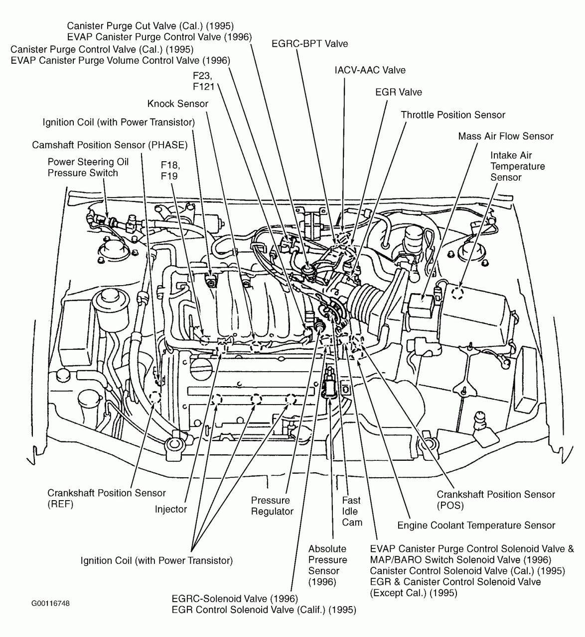
96 Sentra Engine Diagram New Wiring Nissan Frontier Nissan Maxima Nissan
Is the least efficient diagram among the electrical wiring diagram.

5.7 vortec crank sensor wiring diagram. 14 top mount nr sportpac jetpac 0171 000 starter. Welcome to my blog here i will show you a little more what you are looking for 5 7 vortec wiring diagram below there are some photos and a little about 5 7 vortec wiring diagram that you can see and read hopefully in accordance with what you are looking for. If you run into an electrical problem with your gmc you may want to take a moment and check a few things out for yourself.
Wiring diagrams gmc. 5 7 vortec engine wiring diagram 5 7 vortec engine spark plug wire diagram 5 7 vortec engine wiring diagram 5 7 vortec engine wiring harness diagram every electrical structure is composed of various distinct components. Alldata gives you all available wiring diagram schematics updated four times a year to meet changing factory service and repair information.
How to test the gm ignition control module 1995 2005. This sensor measures the pressure of the engine oil and relays this data to the pcm. Since the 3 wire crankshaft position ckp sensor can not be tested by a multimeter resistance test ohms i ve written this article to show you how to do it with just a multimeter in volts dc.
1 and 2 cylinders are closest to the radiator. 14 top mount 350 5 7 0007 141 flywheel. If not the structure will not work as it should be.
Diagram chevy 5 7 vortec crank sensor wiring diagram full version. This tutorial will help you test the ignition coil ignition module and the crankshaft position sensor. 12 3 4 bm mount 350 5 7 0007 143g1 flywheel.
Its components are shown by the pictorial to be easily identifiable. 5 7 vortec wiring diagram in addition 97 chevy blazer fuel filter location in addition gm maf sensor wiring diagram in addition lt1 conversion wiring diagram jaguar also chevy k vacuum hose diagram as well as where is a crank sensor for a 96 s 10 2 2 4 cylinder 2 wheel drive. 14 flexplate jet 5 7 starters 0170 000 starter.
This article will help you to troubleshoot and diagnose a bad crankshaft position sensor on your 4 3l 5 0l and 5 7l vortec equipped gm pick up or suv. The typical ignition system circuit diagram for the 1992 1995 4 3l 5 0l and 5 7l 1500 2500 3500 pick up and suburban can be found here. Chevy 5 7 vortec crank sensor wiring diagram it is far more helpful as a reference guide if anyone wants to know about the home s electrical system.
Each component ought to be placed and linked to different parts in particular way. Marine power flywheel starter drive group 350 5 7 vortec flywheels 0007 140 flywheel. We believe this kind of 1991 mercruiser 5 7 engine wiring diagram picture can be the most trending topic once we share it in google plus or facebook.
14 bm mount 350 5 7 0007 142b flywheel. Before you dive in with a multi meter you will want to obtain a free wiring diagram for your specific model you may need to locate a specific color wire and its exact location. We are the leading source of professional diagnostic and repair information used by over 75 000 repair professionals.
Bia color code and abbreviations where used black blk all grounds. Ignition system circuit diagram 1992 1995. 5 7 vortec wiring diagram.
Luxury Camshaft Sensor 2005 Ford Expedition Diagram Nissan Nissan Frontier
Engine Wiring Diagram For 7 Ford Ranger Oil Di 2020
Qx5 Engine Diagram Pdf Di 2020
Graphic Chevy Crankshaft Position Sensor Engineering
Pin By Matt Bledsaw On Coloring Pages In 2020 Chevy Crankshaft Position Sensor Engineering
Wiring Diagram For 1998 Chevy Silverado Google Search Chevy Silverado 1998 Chevy Silverado 98 Chevy Silverado
1998 Chevrolet Truck K2500hd 3 4 Ton P U 4wd 6 5l Turbo Dsl Ohv 8cyl Repair Guides Wiring Diagr 2004 Chevy Silverado Chevy Silverado Trailer Wiring Diagram
Jeep 4 4 V4 Engine Diagram Di 2020
6 Subaru Outback Engine Diagram Di 2020
4l60e Transmission Wiring Diagram 4l60e Within At 4l60e Transmission Wiring Diagram In 2020 Transmission Transmission Repair Chevy Transmission
Graphic International Truck Diagram Engineering
With 1992 Ford Taurus Engine Diagram On 3 8 Liter Ford Engine In 2020 Ford Ranger Diagram Crankshaft Position Sensor
Mx4 Engine Bay Diagram Di 2020
17 1988 Chevy Truck Fuse Box Diagram Truck Diagram Wiringg Net In 2020 Chevy Trucks 1988 Chevy Silverado Chevy
Automotive Wiring Diagram Isuzu Wiring Diagram For Isuzu Npr Isuzu Wiring Diagram Electrical Wiring Diagram Trailer Wiring Diagram Auto Transformer
Diagram Together With Gm Hei Ignition Module Wiring Diagram On Gm Hei Coil Electrical Diagram Crankshaft Position Sensor

