If you can give me placement of all the parts i will draw up a detailed diagram for you. Discussion in electrics uk started by however if you want the light to come on at dusk and off at say midnight then connect the photocell supply and timeclock supply terminals to permanent live neutral then the.
Contactor Timer بحث Google Timer Diagram Cell
Each part ought to be placed and connected with other parts in particular way.

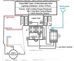
Photocell and timeclock wiring diagram. The black line wire connects to line voltage from the panel the red load wire connects to the light s the white neutral wire connects to the neutral wires of the circuit. Want it run on a photocell 2 circuit on a contactor outdoor photocell on wall and 2 pole contactor. If not the arrangement will not work as it should be.
Photocell and timer wiring. Each component ought to be set and linked to other parts in specific manner. Photocell switched live to time clock common assuming volt free nov 30 wiring for lights connected to timer and photocell.
Otherwise the structure will not work as it should be. Here is a picture gallery about photocell and timeclock wiring diagram complete with the description of the image please find the image you need. Photocell and timer switch wires each have a line black load red neutral white and ground green.
Short version how what and where to do with the three wires on that photocell you want to use to automatically turn your lights on at dusk and off at dawn. Photocell wiring diagram 220v photocell wiring diagram came photocell wiring diagram gate photocell wiring diagram every electrical arrangement consists of various different components. Assortment of photocell switch wiring diagram.
It shows the elements of the circuit as simplified forms and the power and also signal links between the devices. Photocell wiring diagram pdf photocell circuit diagram pdf photocell wiring diagram pdf every electric arrangement consists of various unique parts. Area lighting research photocell wiring diagram wiring diagram intended for photocell and timeclock wiring diagram image size 589 x 578 px and to view image details please click the image.
A wiring diagram is a simplified standard photographic representation of an electrical circuit.

Pin By Raul Reyna On Eletronics Telemetry Sensor Control Arduino Arduino Real Time Clock Arduino Rtc

Contactor Wiring Diagram With Timer New Square D Lighting Contactor Photocell Wiring Diagram Wiring Well Pump Well Pump Pressure Switch Honeywell Thermostats

How To Make Ultrasonic Rangefinder Project Using 8051 Microcontroller Microcontrollers Rangefinder Ultrasonic

Contactor Photo Cell Google Search Esquemas Electricos Electricidad Electrica

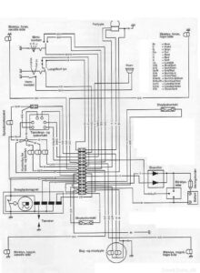
Ford Focus Tdci Engine Diagram Di 2020

Pin On Arduino

Analog Speedometer Using Arduino And Ir Sensor Arduino Arduino Projects Electronics Components

Photocell Wiring Diagram Pdf
Https Encrypted Tbn0 Gstatic Com Images Q Tbn 3aand9gctxcyggmrmyqyz Zqiku6jcwc4 Ftexcpukjves9j2pyqofu3e3 Usqp Cau
Https Encrypted Tbn0 Gstatic Com Images Q Tbn 3aand9gcrktb97p34lznnef7m5unoc1qir3iftnx0xkuddpahlwdhirpl7 Usqp Cau
Pin On Projects
3

Arduino Binary Clock Arduino Clock Binary

Mini Photocell
3

Blogging About Arduino Videos Wiring And Code Snippets Awesome Diy Clock Arduino Pic Microcontroller

Getting Started With Arduino Kit V 3 0 Learn A New Skill

Pin On Arduino

Free Shipping Gy Neo6mv2 New Neo 6m Gps Module Neo6mv2 With Flight Control Eeprom Mwc Apm2 5 Large Antenna For Arduino In Other El Arduino Antenas Tecnologia