The diagram on the pump is unreadable. Ao smith 2 speed motor wiring diagram wiring diagram pool pump motor valid pentair pool pump wiring diagram awesome ao smith 2 speed.
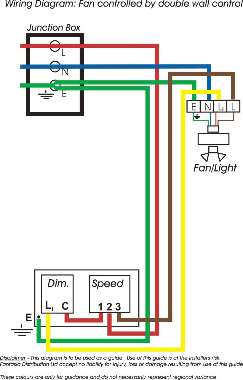
Unique Ced Extractor Fan Wiring Diagram Diagram Diagramsample Diagramtemplate Wiringdiagram Ceiling Fan Switch Ceiling Fan Wiring Ceiling Fan Installation
A wiring diagram is a kind of schematic which utilizes abstract photographic signs to reveal all the affiliations of elements in a system.

2 speed pool pump wiring diagrams. Where do i run the other. A wiring diagram is a simplified traditional pictorial depiction of an electric circuit. Pump runs on low speed but not on high speed.
Century 2 speed motor wiring diagram 2 speed pool pump wiring diagrams awesome wiring diagram symbols automotive century hp ground swimming. Signs that stand for the parts in the circuit as well as. 2 speed pool pump adelindeburnclub.
How to wire 2 speed pump. A jumper between two of the terminals allows for low speed current to pass through to the pool pump. Tried to make it as simple as possible.
Circuitry diagrams are made up of two points. The basic 3 way switch wiring diagram this entry was posted in outdoor wiring diagrams and tagged 2 speed pump 230 volt pump breaker disconnect how to wire a pump pump wiring wiring diagram. Wiring diagram pics detail.
I have a new hayward 2 speed pump with the hi lo switch located on pump the pump motor has 3 terminals i e. There in nothing labeled line in. 2 speed pool pump wiring diagrams unique pool pump timer wiring.
2 speed pool pump wiring diagrams fresh hayward pool pump motor pool exactly what s wiring diagram. 2 speed pool pump motor wiring diagram collection html free download 2 speed pool pump motor wiring diagram collection html 1080p 1920 x 1080 fhd full hd resolution 2k 2048 x 1080 2000 1440p 2560 x 1440 qhd quad hd resolution 1440p hd ready 4k 2160p 3840 x 216 uhd ultra hd resolution 4000 pixels 8k 4320p 7680 x 4320 hd quality file format jpeg jpeg xr jpeg 2000 jpeg xs png webp heif pdf epub. Replacement for hot tub pump ge motor super pump vs variable speed pool pumps are a drop in upgrade that delivers up to 80 energy cost savings over single speed models.
It s basically this diagram. 2 speed motors need to have a third wire the low speed wire coming from the timeclock. I have an off on switch on wall to supply power to the pump.
Collection of 2 speed pool pump motor wiring diagram. I have two hot wires 120v each verified with my volt meter. These types of pool and spa timeclocks are known as dpdt double pole double throw.
A standard intermatic type of pool timeclock t104. I can make out running one hot wire to line 3 or 4. It shows the parts of the circuit as streamlined shapes and also the power and signal links in between the gadgets.
I can t tell from this diagram. 1 2 and 3 4 the wiring points me to wiring line 1 to terminal 1 line 2 to connect to the 3 4 of the terminal.

Diagram Diagramtemplate Diagramsample

Electrical And Electronics Engineering Types Of Motor Control Schematics Electrical Circuit Diagram Circuit Diagram Electronic Engineering

Related Image Pool Pump Submersible Pump Diagram

5 2 Speed 3 Phase Motor Wiring Diagram Addict Throughout In Three Phase Motor Wiring Diagram Diagram Wire Plugs

Volvo Electric Cooling Fan Electric Cooling Fan Volvo Electric Radiator Fan

Pin On Wiring Diagram

3 Relay Cooling Fan Wiring Question Electrical Circuit Diagram Relay Cooling Fan

Ford E350 Wiring Diagram In 2020 Electrical Wiring Diagram Diagram F150

Ah3 Delay Timer And Relay Electrical Circuit Diagram Hvac Design Boiler

Fuse Box Cover Ideas

Ford Scorpio Wiring Diagram Diagram Ford Car

1 4hp 115 Volt 1625rpm 2 Speed Coleman 6757b311 Rv Air Conditioner Motor Ao Smith Orv4538 Rv Air Conditioner Coleman Rv

Snap Crackle Pop Sewing Machine Repair Modern Sewing Machines Bernina Sewing Machine

Gt Gt Eew 39 S Vision Electrical Engineering World Is The Worldwide Com Electrical Engineering Books Electrical Circuit Diagram Electrical Engineering
Three Phase Branch Circuit Diagram Circuit Circuit Diagram Fuses

Danfoss Bd35f Compressor Service Manual

240v Motor Wiring Diagram Single Phase Collection Single Phase Motor Wiring Diagram With Capacitor Electrical Diagram Electric Motor Electrical Circuit Diagram

Split Air Conditioner Wiring Diagram Refrigeration And Air Conditioning Electrical Circuit Diagram Circuit Diagram

Low Speed Fan Resistor We Need Solution North American Motoring Cooling Fan House Wiring Ceiling Fan Wiring