The other terminal is the exciter. The other terminal is the exciter.

At Alternator Diagram Wiring Car Alternator Denso Alternator Alternator
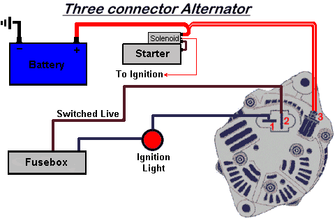
IG is the ignition input that turns on the alternatorregulator assembly.

Alternator Wiring Diagram. R Simply connect one wire from the positive battery terminal to the positive alternator terminal. Its supposed to assist all the typical user in developing a suitable method. 1 Left terminal NO CHARGE WARNING LIGHT Note that our 1-wire.
If you are able to look at a manufacturers diagram of the alternators connectors the wire that slides over Pin 1 of the alternator leads to the positive connection on the vehicles battery and senses voltage. If the voltage rises above or falls below 12 Volts the alternators internal voltage increases or reduces power output to. Step 7 Figure 1 Take the long red 10 gauge wire and connect to the back of the alternator 1032 stud.
This is what excites the field of the alternator. The PDF shown here is for a GM. Tractor Ignition Switch Wiring Diagram – Pinterest Alma Thomas Spring Grass 1973 acrylic on canvasnice starting place for a quilt Spring Grass by Alma Thomas.
Search the Smithsonian American Art museum. The first component is symbol that indicate electrical element from the circuit. Figure 1 below is a block diagram or a functional diagram of an alternator and its connections to the remainder of the automobile electrical system.
The other thing which you will get a circuit diagram would be traces. A typical PCM-controlled alternator wiring diagram with alternator connections going to the battery and PCM. With key on power is then transferred through the no charge indicator light to the 1 spade on the alternator regulator connection.
Gm 3 1 Wiring Wiring Diagram 2 Wire Alternator Wiring Diagram. Should greater accuracy be desired in determining the opti-mal wire gauge the following formula can be used. Simple alternator wiring diagram.
The alternator is charging at least 138 volts 1000 engine RPMs. 4 Wire Alternator Wiring Diagram. Aro Wiring Diagram Wiring Library Chevy Alternator Wiring Diagram.
GM alternator wiring GM alternator wiring. CMK x I x LE whereas CM represents the circular mil area of the conductor K represents the mil-foot resistance of copper I. Wiring Diagram arrives with several easy to stick to Wiring Diagram Directions.
Basic wiring diagram to replace the alternator and the exciter wire pigtail. It includes instructions and diagrams for various types of wiring techniques as well as other things like lights home windows etc. When an alternator has its output disconnected whilst the engine is running the sudden stopping of current flow through the stator causes the magnetic field that was being.
Find this Pin and more on Superior Automotive Technicians Cars by Superior Automotive Technicians. Read electrical wiring diagrams from unfavorable to positive and redraw the signal being a straight collection. Connect alternator to Balmar regulator wiring harness as.
When you make use of your finger or perhaps the actual circuit with your eyes it is easy to mistrace the circuit. The following diagram shows the wiring for a typical 3-wireBatteries and Alternators. Alt Wire Diagram Alternator Wiring And Out The Dash Warning Light 12 Volt Alternator Wiring Diagram.
B is the alternator output wire that supplies current to the battery. These guidelines will likely be easy to grasp and apply. This particular model 10SI used in the 1970s and early 80s is the one youll find on the generation of GM cars most often used in demolition derbies.
There are two things which are going to be present in any Alternator Exciter Wiring Diagram. Valeo Alternator Wiring Diagram Source. Valeo Alternator Wiring Diagram Source.
A circuit is usually composed by many components. Alternator Wiring Diagram Wiring Diagram is the visual representation of a intricate electric circuit. This is the same place the red wire from the DA plug connects.
You simply require to have a great comprehension on. Alt Wire Diagram Alternator Wiring And Out The Dash Warning Light 12 Volt Alternator Wiring Diagram. Take the other end of the long red wire and connect directly to one terminal of.
Balmar Alternator Wiring Diagram Schematics Wiring Diagram 2 Wire Alternator Wiring Diagram. Wiring Diagram consists of numerous detailed illustrations that present the connection of various items. Understanding the Alternator Four wires connect the alternator to the rest of the charging system.
GM has many different alternators and each has its own alternator wiring diagram and alternator symptoms. 1 trick that We 2 to printing a. 2 Wire Alternator Wiring Diagram 3 And Delco Remy Or 3Wire Diagr 2 Wire Alternator Wiring Diagram.
It is really simple to draw a wiring diagram. Wire runs between the alternator and the batteries being charged must be considered. Gm Tps Wiring Wiring Diagram 2 Wire Alternator Wiring Diagram.
Toyota Alternator Wiring Diagram Pdf from static-resourcesimageservicecloud. It represents the physical parts of the electrical circuit as geometric forms with the real power and connection connections in between them as thin sides. Typical Alternator Wiring Diagram Below is a simplified diagram showing connections to the vehicles PCM and battery.
S is used by the regulator to monitor charging voltage at the battery. One wire alternators eliminate the unsightly factory wiring harness and simplifies installation by using only one wire for charging. Alternator Wiring Diagram Wiring Diagram is the visual representation of a intricate electric circuit.
Does it check the vehicles voltage internally or from an outside source. It was also used in a lot of off-road equipment so theyre generally cheap and easy to find. Note the alternative positions for the voltage regulator and also the surge quench diode.
THIS IS THE WIRING DIAGRAM FOR A TYPICAL ALTERNATOR. One of the key differences is how the internal voltage regulator determines charge rate. Print the wiring diagram off plus use highlighters to trace the signal.
This diagram shows how to wire a Delco GM internally regulated 3-wire alternator. This rotor spins past wire coils causing a magnetic field. This diagram shows the simple wiring diagram for negative ground Delco SI series alternators The ignition switch is most commonly powered from the starter battery stud but source may vary depending on application.
All circuits are usually the same. Voltage ground individual component and switches. The Surge Quench Diode.

Lovely Wiring Diagram Alternator Diagrams Digramssample Diagramimages Wiringdiagramsample Wiringdi Electrical Circuit Diagram Voltage Regulator Alternator

Dual Alternator Battery Isolator Wiring Diagram Car Alternator Alternator Automotive Electrical

Installing Turn Signals Motorcycle Wiring Electrical Diagram Electrical Wiring Diagram

Lewmar Windlass Wiring Diagram Upgrade Windlass Power Wiring Of Lewmar Windlass Wiring Diagram With Windlass Wiring Diagram For Windlas Diagram Power Wire Wire

Push Button Ignition Switch Wiring Diagram New Boat Wiring Kill Switch Electrical Wiring Diagram

Starter Wiring Help Electrical Circuit Diagram Electricity Wire

Headlight Relays And 3g Alternator The Swap 6 Ford Alternator Wiring Diagram Emprendedor Link Alternator Car Alternator Automotive Repair

Gm 10si Alternator Wiring Issues The H A M B Alternator Diagram Electrical Wiring Diagram

Sbc Alternator Wiring Diagram Alternator Car Alternator 68 Chevelle

Lovely Wiring Diagram Alternator Diagrams Digramssample Diagramimages Wiringdiagramsample Wiringd Alternator Electrical Circuit Diagram Electrical Diagram

Wiring Diagram Toyota Alternator S Sense Wire Example Denso Alternator Car Alternator Denso Alternator

Gm Alternator Identification Car Alternator Alternator Motorcycle Wiring

Simple Alternator Wiring Diagram Alternator Car Alternator Automotive Electrical

Awesome Three Wire Alternator Wiring Diagram Gm Diagrams Digramssample Diagramimages Wiringdiagramsample W Alternator Electrical Diagram Voltage Regulator

Cdi Wiring Diagram Motorcycle Wiring Kill Switch Electrical Wiring Diagram

Wire Harness Wiring Cdi Assembly For 50 70 90 110cc 125cc Atv Quad Coolster Go Kart Wish Motorcycle Wiring 90cc Atv Chinese Scooters

Lovely Wiring Diagram Alternator Diagrams Digramssample Diagramimages Wiringdiagramsample Wiringd Alternator Electrical Circuit Diagram Electrical Diagram

Unique Wiring Diagram For Chinese 110cc Atv Wiring Diagram Chinese Atv Wiring Diagrams Roketa 11 Motorcycle Wiring Electrical Diagram Electrical Wiring Diagram


