Three wire motor winding connection diagram. Two separate winding and dahlander winding.
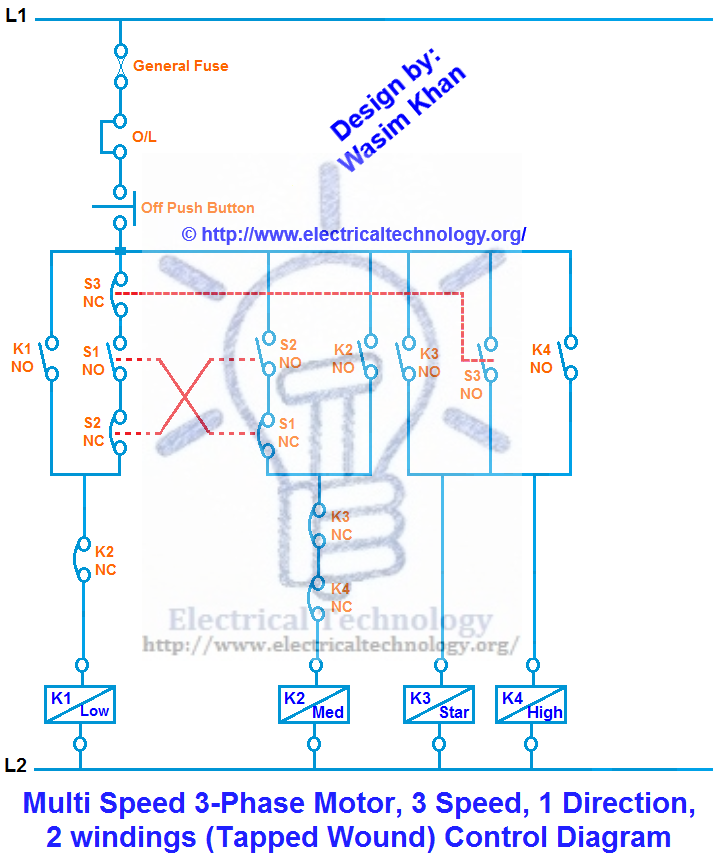
Multi Speed 3 Phase Motor 3 Speeds 1 Direction Power Control Diagrams Electrical Technology Electrical Circuit Diagram Electrical Projects Electrical Diagram
Usa t12 t13 single speed dual voltage low voltage.

2 speed 2 winding motor wiring diagram. Terminal markings and internal wiring diagrams single phase and. Shall have terminal markings as given in mg 1 2 61 for three phase single speed induction motors. 12 lead wye start delta run or pws single voltage assembled in conduit box.
2 speed 2 winding single voltage wye connected with current transformers lightning arrestors surge capacitors. Two speed two winding low speed see motor nameplate high speed see motor nameplate connection dt43 diagram l1 l2 l3 l1 l2 l3 2u 2v 2w 1u 1v 1w t11 t1 t2 t3 t12 t13 2u 2v 2w 1u 1v 1w t11 t1 t2 t3 1093 9p000011 sew eurodrive inc. Diagram dd4 low speed low speed u1 u1 v1 v1 w1 w1 u2 u2 v2 v2 w2 w2 l1 l1 l2 l2 l3 l3 e e high speed red leads.
Two speed electric motors are usually divided into two main groups. Repulsion start induction electric motor reversible a repulsion start induction motor is a single phase motor having the same winding s as a repulsion motor but at a predetermined speed the rotor winding is short circuited or otherwise connected to give the equivalent of a squirrel cage winding. A wiring diagram is a simplified standard pictorial representation of an electric circuit.
In a 3 wire motor three wires are drawn out from the winding of the motor among these one wire is common wire and the other wire is of the running winding and the third wire is drawn in the starting winding. Collection of ao smith 2 speed motor wiring diagram. With the dahlander winding it is only possible to reach a pole number ratio of for example 2 4 4 8 or 6 12.
Wye start delta run or pws connection 12 lead dual voltage. It shows the components of the circuit as streamlined forms and the power as well as signal connections in between the gadgets. The main winding of a single phase motor is designated by t1 t2 t3 and t4 and the auxiliary winding by t5 t6 t7 and t8 to distinguish it from a quarter phase motor which.
Always use wiring diagram supplied on motor nameplate. With 2 separate windings dual winding high speed red leads red leads black leads black leads m 3 single speed only 3ø wiring diagrams u1 red v1 yellow w1 blue thermal contacts tb white l1 l2 l3 n e codes. Two separate winding motor has many desired different polarities which offers the possibility of different speed ratios.

2 Speeds 1 Direction 3 Phase Motor Power And Control Diagrams Electrical Circuit Diagram Electrical Engineering Quotes Basic Electrical Wiring

12 General Electric Induction Motor Wiring Diagram Wiring Diagram Wiringg Net In 2020 Electric Furnace Washing Machine Motor Types Of Electrical Wiring

15 Electric Blower Motor Wiring Diagram Fan Installation Ceiling Fan Installation Ceiling Fan Wiring

Two Speeds Two Directions Multispeed 3 Phase Motor Power Control Diagrams Electrical Technology Electrical Circuit Diagram Power Directions
Single Phase Induction Motor Winding Diagram Electrical Circuit Diagram Electrical Diagram Capacitors

12 30 Jpg 1876 1447 Diagram Diagram Chart Wire

Wiring Diagram For 220 Volt Single Phase Motor Bookingritzcarlton Info In 2020 Electrical Diagram Electric Motor Stepper Motor

Ceiling Fan Speed Control Switch Wiring Diagram Diagrama De Instalacion Electrica Instalacion Electrica Instalacion

Wiring Diagram For Ac Motor Washing Machine Motor Washing Machine Motor Washing Machine Motor

Three Phase Slip Ring Rotor Starter Control Power Power Electric Circuit Electronic Engineering

3 Phase Motor Wiring Diagrams Non Stop Engineering Electrical Circuit Diagram Electrical Wiring Colours Electrical Wiring Diagram

Motor Winding Diagram Delta Connection Electrical Circuit Diagram Electrical Projects Electrical Engineering Projects

How To Wire 3 Speed Fan Switch Ceiling Fan Installation Fan Installation Ceiling Fan Wiring

Two Value Capacitor Single Phase Motor Electric Motor Electrical Circuit Diagram Capacitors

2 Phase Motor Drawings 1 Ecn Electrical Forums Electricity Electrical Code Motor

Three Phase Motor Connection Star Delta Y D Reverse Forward With Timer Power Control Diagram Electrical Technology Electrical Circuit Diagram Circuit Diagram Diagram

Ac Condenser Fan Motor Wiring Diagram 4 Wire Beautiful For New 7 Fan Motor Ceiling Fan Wiring Electrical Circuit Diagram

Wiring Diagram Of Washing Machine Motor Bookingritzcarlton Info Washing Machine Motor Washing Machine Home Electrical Wiring

Rev For Three Phase Motor Connection Power And Control Diagrams Electrical Circuit Diagram Electrical Projects Circuit Diagram