It uses two contactors two auxiliary contact blocks an overload relay a mechanical interlock two normally open start pushbuttons a normally closed stop pushbutton and a power supply with a fuse. The above wiring diagram assumes your magnetic starter has a 240v coil.
Square D Motor Starter Wiring Diagram Solar Panel Battery Electrical Wiring Diagram Solar Panel System
Wiring instructions for magnetic starters important if the compressor has a factory mount ed magnetic starter the starter has been wired to the pressure switch and.

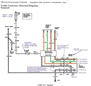
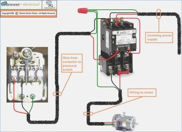
Magnetic starter wiring diagram. Figure 1 typical wiring diagram line diagrams show circuits of the operation of the controller line diagrams also called schematic or elementary diagrams show the circuits which form the basic operation of the controller. Lockout and tag power before performing either of these two procedures. Fig 4 illustrates how to wire the magnetic starter to the motor and pressure switch for further information on magnetic starters refer to form 200 1946 warning.
A wiring diagram typically offers info about the relative setting and also plan of tools and also terminals on the gadgets in order to help in building or servicing the gadget. Wiring instructions for magnetic starters important if the compressor has a factory mount ed magnetic starter the starter has been wired to the pressure switch and motor. Magnetic starter wiring diagrams for 30 amp 120 240 volt coils.
Shut off the main power. 2 troubleshooting the installation warning. Wiring diagrams ww introduction this booklet has been prepared as a guide to some of the useful ways allen bradley s manual and magnetic across the line starters may be applied.
Tm 5 3895 374 24 1 installing the magnetic starter this air compressor requires a magnetic starter to prevent motor damage in the event of a thermal overload. If you have a 120v coil instead of running a line from coil overload l2 you must run coil overload neutral. It reveals the elements of the circuit as streamlined forms and also the power and also signal connections between the gadgets.
If nuisance tripping occurs check for proper heaters loose connections and severe arcing or pitting of contacts. No other electrical connections are required. Figure 1 is a typical wiring diagram for a three phase magnetic motor starter.
It will also serve as a useful aid where simple wiring systems are to be studied. Use the wiring diagrams on the back of this sheet to install and connect power wires for the starter and motor. Collection of cutler hammer magnetic starter wiring diagram.
Connect power and ground leads from a fused disconnect or circuit breaker directly to the magnetic starter. A wiring diagram is a simplified traditional pictorial representation of an electric circuit. Merely ignore the control wiring in red 3ph starter 1ph motor.
This diagram is for 3 phase reversing motor control with 24 vdc control voltage. If the pump rotates backwards as evidenced. When applying these diagrams it is well to.

Magnetic Contactor Schematic Diagram Electrical Circuit Diagram Thermostat Wiring Electrical Wiring Diagram

Magnetic Starter Wiring Diagram Auto Transformer Electrical Diagram Electrical Wiring Diagram

Cutler Hammer Motor Starter Wiring Diagram In Allen Bradley Control Diagrams On Contactor Symbol 715 Gif Dry Type Transformer Diagram Electrical Wiring Diagram

Circuits Formulas And Tables Electrical Engineering Basic Vocational Knowledge 4 Electrical Machines 4 2 Three Electricity Electrical Engineering Motor

Single Phase Motor Contactor Wiring Diagram Elec Eng World Electrical Wiring Electrical Engineering Electricity

Magnetic Contactor Wiring Diagram 4 Electrical Circuit Diagram Circuit Diagram Wire

35 Lovely Square D Manual Motor Starter Wiring Diagram In 2020 Diagram Circuit Diagram Wire

Direct On Line Starter Wiring Diagram Directions Electrical Diagram Dol

Pin By Brian Jones On Tools In 2020 Line Diagram Electrical Diagram Electricity

Wiring Diagram For Motor Starter 3 Phase Controller Failure Relay Electrical Pleasing Three And Contactor Teknik Listrik Rangkaian Elektronik Listrik

Wiring Diagram Of Magnetic Contactor Electrical Circuit Diagram Circuit Diagram Auto Transformer

Magnetic Contactor Connection Diagram Magnetic Contactor Connection Diagram With In 2020 Electrical Circuit Diagram Electrical Wiring Diagram Basic Electrical Wiring

Shihlin Motor Starter Wiring Diagram Wire Switch Electrical Wiring Power Source

Direct On Line Dol Motor Starter Basic Electrical Wiring Electrical Circuit Diagram Circuit Diagram

Single Phase Motor Wiring With Contactor Diagram Circuit Diagram Electrical Circuit Diagram Electrical Wiring Diagram

Forward And Reverse Motor Starter Wiring Diagram Elec Eng World Electrical Circuit Diagram Circuit Diagram Electrical Diagram
Dol Starter Panel Wiring Diagram Save Start Stop And Motor Electrical Circuit Diagram Circuit Diagram Electric Circuit

Direct On Line Dol Wiring Diagram For 3 Phase With 110 230vac Control Circuit Electrical Circuit Diagram Circuit Diagram Electrical Wiring Diagram

Wiring Diagram For 220 Volt Air Compressor Bookingritzcarlton Info Air Compressor Pressure Switch Compressor Diagram