Each component ought to be placed and linked to other parts in specific manner. T w 6.

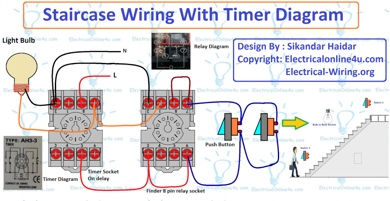
This Post Is About The Staircase Timer Wiring Diagram In The Diagram I Use The On Delay Timer Finder 8 Pin Relay Re Electrical Circuit Diagram Timer Diagram
It s meant to help each of the average user in developing a proper system.

Start stop push button switch wiring diagram. These guidelines will probably be easy to grasp and use. C i m n c. Otherwise the arrangement won t work as it ought to be.
With such an illustrative manual you will be capable of troubleshoot stop and total your projects with ease. Start stop push button wiring diagram emergency stop push button wiring diagram start stop push button station wiring diagram start stop push button switch wiring diagram every electrical structure consists of various different parts. With this sort of an illustrative manual you are going to have the ability to troubleshoot prevent and complete your projects without difficulty.
A wiring diagram is a streamlined standard photographic representation of an electrical circuit. Push button starter switch wiring diagram push button ignition switch wiring diagram push button start switch wiring diagram push button starter switch wiring diagram every electrical arrangement consists of various distinct parts. It also pulls in a contact that is tied in parallel with the start button giving it another path for current flow once your release the start button.
When you press the start button and the stop button is not pressed the 24vdc relay energizes and it pulls in the r1 contactor that feeds three phase power to the motor. Otherwise the structure won t function as it ought to be. Assortment of start stop push button station wiring diagram.
Push button start stop switch wiring diagram electricity site push button starter switch wiring diagram. Start stop push button wiring diagram you will want a comprehensive professional and easy to understand wiring diagram. Wiring diagram comes with a number of easy to stick to wiring diagram guidelines.
Pilot light l2 4 2 3 pilot light start stop bulletin 1495 normally closed auxiliary contacts are required. Push button starter switch wiring diagram. Simple wiring for toggle switch and push button start this is how to run wiring for a toggle on off switch and a push button start this is the most basic wiring you need to run your mower 800 2 0 typical wiring diagrams for push button control typical wiring diagrams for push button control push button circuit wiring diagram 0 0 4 multi station with.
Start stop switch wiring diagram you will need an extensive skilled and easy to understand wiring diagram. Typical wiring diagrams for push button control stations 7 start stop control wiring diagrams single station with motor stopped pilot light l1 start l2 i 1 stop 2 oi 3 n w o l. Each part should be placed and connected with other parts in particular way.
It reveals the parts of the circuit as simplified forms as well as the power and also signal links between the tools.

15 Car Start Button Wiring Diagramcar Push Button Start Wiring Diagram Race Car Push Button Start Wiring In 2020 Automotive Electrical Boat Wiring Keyless Entry Car

Direct Online Starter Dol Starter Wiring Diagram Diagram Electronic Engineering Motor

New Motor Wiring Diagram Explained Motorcycle Wiring Electrical Diagram Electrical Wiring Diagram

Diagrams Digramssample Diagramimages Wiringdiagramsample Wiringdiagram Electrical Diagram Diagram Diagram Design

Cutler Hammer Motor Starter Wiring Diagram In Allen Bradley Control Diagrams On Contactor Symbol 715 Gif Dry Type Transformer Diagram Electrical Wiring Diagram

Single Push Button On Off Logic Example Ladder Logic Electrical Circuit Diagram Plc Programming

Relay Contactor With Push Button On Off Control Electrical Circuit Diagram Electrical Diagram Relay

Start Stop Push Button Wiring Diagram Single Phase Awesome In 2020 Electrical System Switches Wire

Electrical Diagrams Relay Contactor With Push Button On Off Control Electrical Circuit Diagram Electrical Projects Basic Electrical Wiring

Image Result For Push Start 3 Phase Motor On Switch Circuit Electrical Diagram Reverse Ladder Logic

3 Phase Motor Star Delta Control Circuit Diagram With 8 Pin On Delay Timer Normally Open And Normally Close Push Button Switches Circuit Diagram Timer Circuit

Unique Wiring Diagram For Emergency Stop Button Diagram Diagramsample Diagramtemplate Wiringdiagram Diagram Thermostat Wiring Trailer Light Wiring Diagram

Car One Start Stop Engine System Lock Ignition Button Keyless Entry System Go Push Button Engine Start Stop Button Car Accessory Electrique Tracteur

Boat Building Standards For 12v Switch Panel Wiring Diagram Mesmerizing Sevimliler Power Wheels Power Wheels Jeep Boat Building

Chinese 7cc Engine Diagram Name Di 2020 Honda Diagram Mesin

Unique Wiring Diagram For Emergency Stop Button Diagram Diagramsample Diagramtemplate Wiringdiagram Diagramchart Electrical Diagram Diagram Diagram Design

Honda Ct70 Wiring Diagram With Electrical Pics To Motorcycle Wiring Electrical Wiring Diagram Electrical Diagram

New Mk Emergency Key Switch Wiring Diagram Diagram Diagramsample Diagramtemplate Wiringdiagram Diagramchart Wor Electrical Diagram Diagram Diagram Design

Xrm6 Engine Diagram Original In 2020 150cc Electrical Diagram Electrical Wiring

