531 inches high by 237 inches wide by 181 inches deep. Youll be able to usually rely on Wiring Diagram as an important reference that will help you save time and cash.

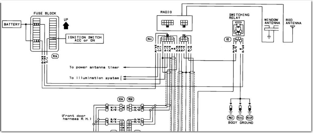
2009 08 29 163245 Bose1 To 2004 Nissan Maxima Wiring Diagram Nissan Altima Nissan Nissan Sentra
Chamberlain garage door opener wiring diagram You will need an extensive skilled and easy to comprehend Wiring Diagram.

3 Button Garage Door Opener Wiring Diagram. A wiring diagram usually gives recommendation not quite the relative face and harmony of. Wiring Diagram Pics Detail. If this does not operate the garage door but the AS-9554 control module clicks when operating the programmed transmitter then wire the unit as shown in diagram 4.
It shows the components of the circuit as simplified shapes and the gift and signal contacts between the devices. Each button has two connections one on each side of the button. Just plug a plug directly in the outlet for the 120 volt part.
3 Button Control Station. With all the help of the e-book youll be able to effortlessly do your own wiring assignments. It will come with a 3 foot cord end on it.
Otherwise the structure wont. Magnetic Door Switch Wiring Diagram Sample. Garage door opener remotes are used primarily in.
We usually ship these garage door opener button stations the business day after you place your order. 3 button Garage Door Opener Wiring Diagram wiring diagram is a simplified agreeable pictorial representation of an electrical circuit. In stock and ships today.
The first white wire connects to the first silver prong on the terminal block. On most of our 3-button control stations the three buttons connect with metal tabs on the right side. With this kind of an illustrative guide you are going to have the ability to troubleshoot stop and complete your tasks with ease.
Pin On Garage Shop 1476 ELECTRICAL BOX some material was on hand. The black wire connects to the gold prong on the terminal block. Each component ought to be set and linked to other parts in specific way.
The 3bxt push button commercial garage door opener exterior control features separate open close and stop buttons that allow you to control your commercial garage door or gate from afar. The back of the motor has 3 screw terminals numbered 1 2 3. The red and the blue wire go to the capacitor.
For garage doors Gates and any other device up to 110V where open close Stop functionality is required. Image Result For 3 Phase Wiring Diagram Australia Regulations Current Transformer Light Switch Wiring Electricity. North shore commercial door offers fast shipping on the pbs 3 opener models.
3 button Garage Door Opener Wiring Diagram wiring diagram is a simplified agreeable pictorial representation of an electrical circuit. This is the common side of the 3-button control stations that wires to the common terminal of the operator. 3 Button Garage Door Switch Wiring Diagram – Hoist Control Circuit – YouTube You need to make sure that you choose an opener you can rely on when you need it most for safety and convenience reasons.
The high voltage wire harness has 6 wires 1 blue 1 red 1 orange 1 black and 2 white wires that connect to the logic board. We also carry the one button pbs 1. 29595 479 S.
NEMA 1 steel enclosure indoor surface-mount installation. Find the grounding terminal for the opener. The wire is run to the openclose relay on your garage door opener or gate operator.
4 If the switch for your garage door opener is unknown first try wiring the unit as shown in diagram 3. Attach the striped redwhite wire under screw terminal 1. Go to the garage door opener and place a live eye on the opener unit.
How do you wire a garage door opener push button. Commonly referred to in the garage door industry as LCE-3. Craftsman 34 garage door opener wiring diagram.
This is where the door control and safety sensors are wired. 3 button garage door opener wiring diagram wiring diagram is a simplified agreeable pictorial representation of an electrical circuit it shows the components of the circuit as simplified shapes and the gift and signal contacts between the devices. We also carry the one-button PBS-1 and the two-button PBS-3 garage door openers.
Variety of wiring diagram for liftmaster garage door opener. And receiver terminal 2 and opener terminal screw 3. Relays generally have 4 pins marked 85 86 30 87 or 5 pins 85 86 30 87 87a.
Genie Excelerator User Manual Garage Door Opener Manuals And Guides L0703287. North Shore Commercial Door offers fast shipping on the PBS-3 opener models. The PBS-3 Garage Door Openers are simple to install on single or multiple gates and garage doors.
Youll be able to usually rely on Wiring Diagram as an important reference that will help you save time and cash. Connect paired grey receiver wires to the opener terminal screws used for the wall push button. Works on any commercial overhead door garage door opener.
Installation and wiring instructions can be found in the manual for Medium-Duty Logic Operators. Genie Garage Door Opener Wiring Diagram genie garage door opener button wiring diagram genie garage door opener circuit board schematic genie garage door opener electrical schematic Every electric structure consists of various diverse parts. In addition to the Commercial Garage Door Opener PBS-3R Three-Button Station North Shore Commercial Door also offers the PBS-1 PBS-2 and standard PBS-3 models in our selection.
Look for the final ground terminal on the garage door openers remote control. Garage door opener no. Press the door control the opener should respond.
3 Button Garage Door Wiring Diagram For Control Wiring Diagram Garage Door Opener Wiring Diagram. 3-Button Indoor Surface Mount Station. To wire the door control.
Typically low voltage wires are ran from the terminals on the opener or device to this control station. Garage door opener wiring diagram Elegant Craftsman Garage Wiring Diagram Door Opener I47 In Stunning. 38245 Purchased from Sanford and Son.
Attach the solid white wire under screw terminal 2. The 3-button control stations has three buttons open close and stop. 3 Button Garage Door Wiring Diagram For Control Wiring Diagram Garage Door Opener Wiring Diagram.
The standby generator and the transfer switch are installed by a professional to the homes existing electrical wiring. Overhead Door Wiring Diagram wiring diagram is a simplified welcome pictorial representation of an electrical circuit. Also connect bell wire to receiver terminal 1 and opener terminal screw 1.
With all the help of the e-book youll be able to effortlessly do your own wiring assignments. Each part ought to be placed and connected with different parts in specific way. 1 without transformer Refer to Figure 3 for wiring connections.
This Three-Button Commercial Garage Door Opener Station PBS-3 features a convenient three-button style that operates the open close and stop commands on y. Chamberlain Garage Door Opener Wiring Diagram chamberlain garage door opener circuit board schematic chamberlain garage door opener circuit diagram chamberlain garage door opener electrical schematic Every electrical structure consists of various unique parts. To wire the safety sensors.

Best Of Genie Garage Door Sensor Wiring Diagram Garage Door Sensor Liftmaster Garage Door Garage Doors

Es200 Wiring Diagram Connection Scheme Automatic Sliding Doors Diagram Exterior Patio Doors

Genie Garage Door Sensor Wiring Diagram For Opener With 1024 0 Garage Door Opener Garage Door Sensor Garage Doors

Block Diagram Of Engine Control Unit Diagram Design Electrical Wiring Diagram Diagram

Install Garage Electrical Wiring Electrical Diagram Electrical Wiring House Wiring

Awesome Genie Garage Door Opener Sensor Wiring Diagram Liftmaster Garage Door Unique Garage Doors Garage Doors

Click This Image To Show The Full Size Version Diagram Xs650 Wire

2001 Ford Taurus Radio Wiring Diagram House Wiring Electrical Wiring Diagram Truck Stereo

Cantilever Sliding Gate Xueming Sliding Gate Electric Gates Gate Motors

2021 Bmw Garage Door Opener Price Electrical Wiring Diagram Dimmer Switch Home Electrical Wiring

Es200 Wiring Diagram Connection Scheme Automatic Sliding Doors Exterior Patio Doors Diagram

Wiring Diagram For A Gas Furnace Fresh Mobile Home Coleman Gas Furnace Wiring Diagram Mobile Home Coleman Of Wiring Diag Electric Furnace Diagram Diagram Chart

Upright Scissor Lift Wiring Diagram Diagram Scissor Lift Wire

Genie Garage Door Sensor Wiring Diagram Automatic Garage Door Opener Chamberlain Garage Door Opener Garage Doors

Wiring Diagram For Driveway Gate With Telephone Entry Electrical Wiring Diagram Driveway Gate Electrical Wiring

High Resolution Garage Door Opener Wiring 10 Genie With Diagram For Liftmaster Garage Door Opener Automatic Garage Door Garage Door Keypad

Liftmaster Garage Door Opener Sensor Wiring Electric Garage Doors Garage Doors Garage Door Opener

Wiring Diagram For Liftmaster Garage Door Opener Liftmaster Garage Door Opener Liftmaster Garage Door Garage Door Sensor

Knock Lock Knocklock Knock To Unlock Garage Doors Unique Garage Doors Craftsman Garage Door

