Voltmeter instructions wire nut flat washer nut washer voltmeter grommet u bracket do not leave any hardware out of these connections diagram 1 ground source step 2 should be connected as shown in diagram 1 to the voltmeter s connection post marked. Toll free customer service.
Pin On Gauges
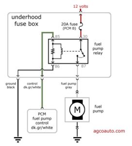
Autometer voltmeter wiring diagram perfect modern voltmeter gauge autometer gauge wiring diagram.

Autometer voltmeter wiring diagram. Short sweep electric gauges. Take the negative wire from the voltmeter and make a good connection on a grounded screw in the car. Toll free tech support.
413 w elm st. The wire from the fuse box step 3 should. Autometer has designed their tach to be used with four six.
Wiring diagram not just offers detailed illustrations of everything you can perform but in addition the processes you ought to stick to whilst carrying out so. Connect one 1 of the light wires white to the dash lighting circuit or to a 12v switched circuit. Replace light bulb with the same.
A wiring diagram is a streamlined standard pictorial representation of an electrical circuit. Wiring your new autometer tachometer into your car will complete the installation. Wire connect the terminal to a clean rust paint free ground.
Not merely can you locate various diagrams however you also can get step by step. Voltmeter wiring figure 5. 1 16 diameter gauges mount in 2.
Once you have selected a mounting location you can run the four wires that operate the tachometer. Using 18 gauge wire connect the terminal to a switched 12v source. This is the voltage that the gauge will indicate.
Variety of autometer tach wiring diagram. Step 6 connect positive wire. These gauges can be mounted in dash or in auto meter mounting solutions panels cups pods etc.
If you have questions regarding the operation or installation of your instrument s please contact auto meter technical service at 866 248 6357. Connect to 12 volt lighting. Use one of the wires that you found in the wiring harness and cut it between the steering column and connector in the dash.
1 16. Contact auto meter service if help is needed in determining your sender resistance. Connect the end coming from the steering column to the voltmeter.
Number bulb as the one removed. The tachometer is designed to show the engine rpms or rotations per minute. It reveals the components of the circuit as simplified shapes and also the power and also signal connections in between the devices.

Pin On Oldens

Pin On Aftermarket Mods

Autometer 2636 Z Series Electric Differential Temperature Gauge In 2020 Gauges Automotive Solutions Automotive Repair

Pin On Gauges

Pin On Enthusiast Merchandise

Pin On Automotive Lighting And Electrical

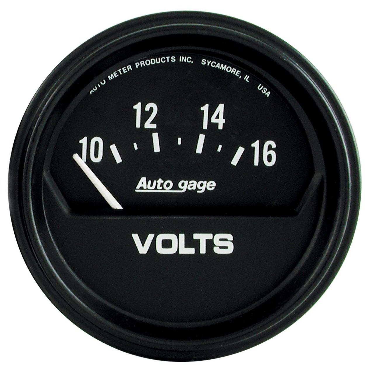
Autometer 1483 Designer Blackt Voltmeter Gauge Multicolor Automotive Solutions Oil Pressure Autometer Gauges

Tachometer Wiring Diagrams Car Gauges Diagram Wire

Dc Ammeter Shunt Wiring Diagram L Fd8e3c77ca6fd112 Gif 1479 786 Car Amplifier Car Amp Diagram

Autometer 3647 Sport Comp Ii Electric Pyrometer Gauge Kit Walmart Com Gauges Led Warning Lights Electricity

Pin On Automotive Lighting And Electrical

Pin On Gauges Car And Truck Parts

Sponsored Ebay Autometer 3516 Sport Comp Electric Fuel Level Gauge Gauges Pro Comp Electricity

Pin On Lighting Electrical

Pin On Gauges Car And Truck Parts

Pin On Lighting
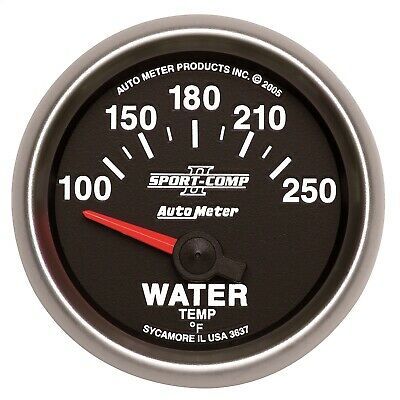
Sponsored Ebay Autometer 3637 Sport Comp Ii Electric Water Temperature Gauge Gauges Electricity Automotive Solutions
Pin On Bricolaje

Autometer 5652 Elite Series Oil Pressure Gauge Fuel Pressure Gauge Gauges Water Pressure Gauge