A 3-wire NM connects the travelers of the dimmer to the travelers of the 3-way switch. For instance when a module is powered up and it also sends out a new signal of fifty percent the voltage in addition to the technician does not know this hed think he offers a challenge.
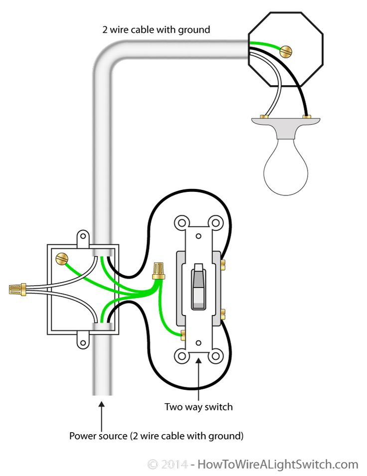
2 Way Switch With Power Feed Via The Light Switch How To Wire A Light Switch Light Switch Wiring Home Electrical Wiring House Wiring
The wiring diagram is a bit confusing showing a Hot wire a load wire and Neutral wire.

Cooper Dimmer Switch Wiring Diagram. Other HALO Home Controllers like the Accessory Switch Accessory Dimmer Anyplace Dimmer or Multi-Room Scene Keypads can also be used. The switch will turn onoff the load only at the brightness level selected at the dimmer Do not exceed maximum rating of sensor as indicated on the strap Use only 14 or 12 copper wire with this device for the line and load connections. Cooper Dimmer Switch Wiring Diagram.
Cooper dimmer switch wiring diagram. Youll be able to often depend on Wiring Diagram being an crucial reference that can help you save money and time. All circuits are the same.
Wire the Leviton combination switch and receptacle onto the power supply and fixture wires. Cooper 3 Way Dimmer Switch Wiring Diagram Source. Leviton Ip710-lfz Wiring Diagram.
Cooper 3 way dimmer switch wiring diagram yellow wire. Cooper 3 way light switch wiring diagram. Wiring a 3-Way Light Switch.
I print the schematic in addition to highlight the circuit Im diagnosing in order to make sure I am staying on the particular path. Cooper 3 Way Switch Wiring Diagram Cooper 3 Way Switch Wiring Diagram Bcberhampur org is one of the pictures that are related to the picture before in the collection gallery uploaded by. Certifications Compliances KEYe.
PS518185EN page 3 March 11 2021 146 PM Multi-Location Control Overview 3-Way Wiring Diagram 4-Way Wiring Diagram Multiple Accessory Switches can control the same smart lightsdevices for easy 3- or 4-way control. To properly read a electrical wiring diagram one offers to know how typically the components in the program operate. Connect the Motion Sensing Switch as shown in the diagram below.
Read typically the schematic like a new roadmap. 4-way Switch Wiring Diagram wiring diagram is a simplified gratifying pictorial representation of an electrical circuit. 4-way switch diagrams are purposed to illustrate the 4 way switch wiring which is used control lights with three or more switchesLighting Wiring Additional Light To A 3-Way Switch Switch.
Wiring Diagram contains the two examples and step-by-step instructions that might allow you to definitely actually construct your undertaking. Units feature a preset ONOFF switch that automatically returns controlled lights to. 5603 2 Decora Rocker 3 Way Ac Quiet Switch In Brown Leviton.
Fully explained 3 way dimmer switch wiring diagram will take the mystery out of wiring a 3-way dimmer switch. Lutron 3-wire LED dimming wiring diagram Lutron 3-wire LED dimmer switch switched hot black Electrical Panel hot black 120V277V ground ground dimmed hot orange LED pendant. If you are using a dimm.
This is a single pole light switch and should be wired as any. 3-Way Switch Wiring Diagram NM Cable A very common type of 3-way electrical diagram is when the power supply wire moves from one switch to the second switch and finally terminates at the fixture. Dimming for 0-10 Volt compatible dimmable light sources.
Cap off the dimmers yellow lead with a wire nut making sure Philips recommends using Leviton brand. 2021 Cooper Lighting Solutions All ights eserved. By Jeanette Gauani March 20 2019.
Leviton single pole dimmer switch wiring diagram. DO NOT USE WITH ALUMINUM WIRE. L and N indicate the supply.
Using the latest in dimming technology Eatons dimmers let you adjust the level of your lighting at the light switch so you can bring the right look to the room and save money at the same time. I recently installed a pair of Cooper 6107 3-way motion switches in a hallway to control a single light. Wiring a 3 way switch new dimmer has aluminum ground can i attach to copper rf9601 z wave plus wireless user manual users cooper devices sensor doityourself com community forums how install single pole decorator wall aqlighting diagram light and replacement diy.
How To Wire Cooper 277 Pilot Light Switch Leviton 3 Way Dimmer Switch Wiring Diagram. Step 4 Connect wires per WIRING DIAGRAM as follows. SWITCH DIMMER YL Black Thumbwheel TOP Green or Bare White Thumbwheel Slider 3-Way Wiring Diagram INC HAL LEDCFL FLR MLV ELV Wiring Diagrams NoteeLocation of terminal screws are color-coded with BK or YL.
Notee3-way switch must be used at the other locations. Take a closer look at a 3 way switch wiring diagram. Cooper Dimmer Switch Wiring Diagram.
The exact fuse chart in your BMW 3-Series may be different. Specifications and dimensions suect to change without notice. Here is a picture gallery about leviton timer switch wiring diagram.
The 0-10V Decorator Dimmer provides full-range classic linear-slide. The black line wire connects to the common terminal of the 3-way dimmer. Before reading a schematic get common and understand all the symbols.
Leviton 6b42 dimmer wiring diagram. Cooper light switch wiring. This can be useful for the two the people and for specialists whore searching to find out more regarding how.
In the diagram below a 2-wire NM cable supplies power from the panel to the dimmer box. Instructions for Dimmer Switch Wiring. Eaton dimmer switch wiring diagram.
1989 Ford Festiva Wiring Diagram 3000gt Wiring Diagram Solar Charger Circuit 1998 Chevy Blazer Brake Switch Wiring Diagram 2009 Mini Cooper Engine Diagram E Ton 90cc Wiring Diagram Step By Step 1963 Chevrolet Carsplete Set Of. Cooper 3 way dimmer switch wiring diagram ford dimmer switch wiring diagram leviton 3-way dimmer wiring installation lutron dimmer switch wiring diagram wiring a gfci with switch dual dimmer switch wiring diagram gfci wiring schematic dimmer switch installation diagram 2195carrera-rennweltde. Cooper Dimmer Switch Wiring Diagram.
E6000 is formulated to meet high performance industrial requirements. Effectively read a wiring diagram one provides to find out how the components inside the system operate. Only one sensor can be used in a 3-way circuit with a switch.
Cooper lighting home security system motion sensor user manual. Cooper 3 Way Dimmer Switch Wiring Diagram Source. Wiring option includes push-in back and side-wiring for quick installation.
Traveler wires are interchangeable on each switch. Wiring Diagrams page 3 Dimensional and Mounting Details In-Wall Smart Switch. At the third touch the bulb is driven fully.
Thats because lighting controls reduce the amount of electricity used by your lights which saves electricity reduces utility bills and extends the life of the bulb. These units are ideal for light commercial applications and are compatible with decorator style devices and wallplates. This might seem intimidating but it does not have to be.
Single Pole Wiring Diagram INC 3-Way Wiring Diagram INC HOT 120V AC NEUTRAL WHITE BLACK B K BLAC K GREEN Single Pole Wiring Diagram Fully Variable Fan Single Pole Wiring Diagram INC3-Speed 4-Speed Fully Variable Fan Wiring Diagrams Rotary dimmers fan controls Electrical Sector 203 Cooper Circle Peachtree City GA 30269 United States. Cooper 3 Way Dimmer Switch Wiring Diagram Source. A plug and play lighting control system composed of room controllers with three relays three 0-10 VDC dimming outputs and complementary low voltage devices wallstations sensors receptacle control that eliminates the commissioning cost.
3 Pole 4 Wire. Cooper Dimmer Switch Wiring Diagram Diagram 3 Way Switch To Dimmer Wiring Diagram Full Version Hd Quality Wiring Diagram Avdiagrams Fanscalcio It. CULus NOM Catalog No.
In-Wall Smart Switch Cooper Lighting Solutions 1121 Highway 4 South Peachtree City GA 302 P 0-4-400.

Wiring Diagram 3 Way Switch With 2 Lights Wiring Diagram Light Switch Wiring 3 Way Switch Wiring Home Electrical Wiring

5 Way Switch Electrical Diy Chatroom Home Improvement Forum Electrical Switch Wiring Light Switch Wiring Electricity

Unique Wiring Diagram For Chinese 110cc Atv Wiring Diagram Chinese Atv Wiring Diagrams Roketa 11 Motorcycle Wiring Electrical Diagram Electrical Wiring Diagram

3 Ways Dimmer Switch Wiring Diagram Basic 3 Way Dimmers Switches A 3 Way Dimmer Switch Is Very Sim Light Switch Wiring Ceiling Fan Switch 3 Way Switch Wiring

On Off Switch Led Rocker Switch Wiring Diagrams Oznium Boat Wiring Automotive Electrical Automotive Repair

Unique Wiring Diagram For Chinese 110cc Atv Wiring Diagram Chinese Atv Wiring Diagrams Roketa 11 Motorcycle Wiring Electrical Diagram Electrical Wiring Diagram
Installation Of Single Pole 3 Way 4 Way Switches Wiring Diagram Electrical Wiring Home Electrical Wiring Electrical Switch Wiring

Lewmar Windlass Wiring Diagram Upgrade Windlass Power Wiring Of Lewmar Windlass Wiring Diagram With Windlass Wiring Diagram For Windlas Diagram Power Wire Wire

Eb Headlight Switch Wiring Diagram Jeep Cherokee Headlights Jeep Cherokee Electrical Diagram

How To Turn A Pump On Or Off From Any Of 12 Switches Home Improvement Stack Exchange Light Switch Wiring Wire Switch House Wiring

Light Switch Wiring Diagram Multiple Lights Home Electrical Wiring Light Switch Wiring Installing A Light Switch

Wiring Diagram For Two Switches Controlling Two Lights Light Switch Wiring Home Electrical Wiring 3 Way Switch Wiring

3 Way Switch Wiring Diagram Light Switch Wiring 3 Way Switch Wiring Electrical Wiring Diagram

Headlight Switch Wiring Diagram Ford Trucks Chevy Trucks Light Switch Wiring

4 Way Switch Wiring Diagrams Light Switch Wiring Electrical Wiring Diagram Home Electrical Wiring

New Wiring Diagram For Light Switch Diagram Wiringdiagram Diagramming Diagramm Visuals Visualisation Light Switch Wiring Electrical Switch Wiring Diagram

2 Way Switch With Power Source Via Light Fixture How To Wire A Light Switch Home Electrical Wiring Light Switch Wiring Basic Electrical Wiring

Push Button Ignition Switch Wiring Diagram New Boat Wiring Kill Switch Electrical Wiring Diagram

Unique Yamaha Moto 4 Wiring Diagram Yamaha Golf Carts Electric Golf Cart Diagram