To measure the spinning resistance of the crankshaft sensor use an ohmmeter multimeter. Crankshaft position sensor wiring diagram.
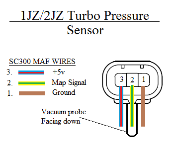
Toyota Map Sensor Pinout In 2020 Map Sensor Electrical Circuit Diagram Toyota
P0339 crankshaft sensor circuit intermittent interruption the honda bulletin 16 011 states that the most likely cause is corrosion between the engine harness and the crankshaft sensor connector.

Crank sensor wiring diagram. Honda recommends replacing the wiring harness and crankshaft sensor with updated parts that correct the corrosion problem. Motorsports ecu wiring harness construction rb racing. This information on testing the 2l chrysler crankshaft sensor pertains to.
P0018 crankshaft position. When the crankshaft position sensor fails it ll fail in one of two ways. A wiring diagram makes it easier to check for shorts to ground or power and of course check for continuity between the crank sensor and the pcm.
It ll fail completely and the engine won t start. You can find the ignition system wiring diagram here. 1993 1995 fuel pump wiring diagram jeep 4 0l.
Crankshaft sensor diagnosis with an ohmmeter. The illlustrations and info in this page apply only to 1996 1997 1998 dodge ram pickups vans and dakota with a 3 9l 5 2l or 5 9l gasoline engine that use the 3 connector pcm. Bmw e90 eccentric shaft position sensor pelican parts.
Wiring diagrams gmc. In the absence of any problems you can move on to finding hidden issues in the wiring diagram of the device. Wiring diagram crankshaft position sensor solved would the code po113 iat sensor have your car fixya.
Have your helper crank or start the engine. Properly functioning sensor will range from 550 to 750 ohms. A failure in.
Ignition system circuit diagram 1997 1999 5 2l dodge dakota and durango. Chrysler 2 0l 4 cylinder crankshaft position sensor ckp 1996 1997 1998 dodge plymouth vehicles with the single overhead and double overhead cam sohc dohc 2 0l engine. Touch one of your meter probes to either one of the sensor wires and the other to the other wire.
In most cases you ll see a fluctuating signal. Symptoms of a bad crankshaft position sensor. If you run into an electrical problem with your gmc you may want to take a moment and check a few things out for yourself.
If neither wire has current there s a failure in the sensor circuit. 2l chrysler crankshaft sensor wiring diagram test 2 0 chrysler crankshaft sensor. P0335 nissan description the crankshaft position sensor also known as the crank position sensor is an electronic device used in an engine to record the rate at which the crankshaft is spinning this information is used by the electronic control module to control ignition and fuel injection the sensor system consists of a rotating part typically a disc as well as a static part the actual.
Check your meter display and compare your reading to your manual specifications. Before you dive in with a multi meter you will want to obtain a free wiring diagram for your specific model you may need to locate a specific color wire and its exact location. Wiring car repair diagrams mitchell 1 diy.

Pin On Crank Sensor Test

Pin On Auto Electrical
Diagram Together With Gm Hei Ignition Module Wiring Diagram On Gm Hei Electrical Diagram Coil Crankshaft Position Sensor

Map Sensor Wiring Diagram Map Sensor Automotive Repair Car Repair Diy

See The Chevy Three Wire Throttle Position Sensor Wiring Diagram Chevytrucks Sensor Custom Chevy Trucks Throttle

Pin Di Wiring Diagram


16 Map Sensor Wiring Diagram Engine Map Sensor Sensor Map

Distributorless Ignition System Dis Ignition System Crankshaft Position Sensor System

Home Lbcc In 2020 Crankshaft Position Sensor Coil Spark Tester

Gm Hei Distributor And Coil Wiring Diagram Diagram Msd Wire

Obd1 Honda Wiring Diagram Http Bookingritzcarlton Info Obd1 Honda Wiring Diagram Diagram Crankshaft Position Sensor Sensor

Megasquirt Wiring Diagram Thumbnail Motorcycle Wiring Automotive Electrical Fuel Injection

Engine Brake Diagram Nissan Di 2020

Yamaha Warrior Wiring Diagram The Wiring Diagram Readingrat Crankshaft Position Sensor Yamaha Diagram

Kinetic Honda Wiring Diagram Bookingritzcarlton Info Crankshaft Position Sensor Diagram Circuit Diagram

Dodge Neon Srt4 Tps Wiring Diagram Google Search Libros De Mecanica Automotriz Curso De Mecanica Automotriz Mecanica Automotriz

Ignition System Basic Operation Crankshaft Position Sensor Coil Spark Tester

21 Best Sample Of Ford Wiring Diagrams Samples Bacamajalah In 2020 Ford Ranger Diagram Crankshaft Position Sensor