Simply match the correct colors to each function – video power and RS485. Video Balun Wiring – with a Bridge.
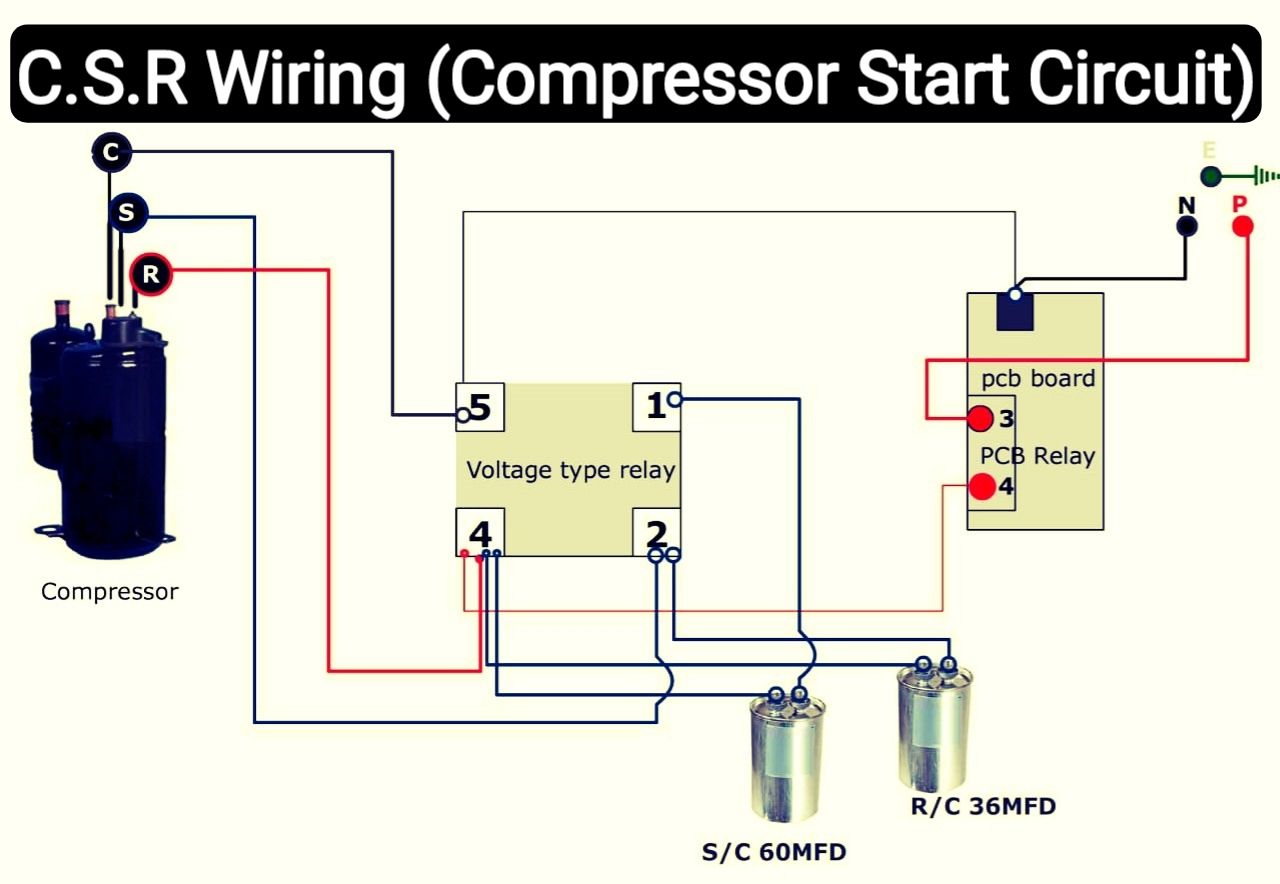
Air Conditioner C S R Wiring Diagram Compressor Start Full Wiring Fully4 Air Conditioner Maintenance Refrigeration And Air Conditioning Hvac Air Conditioning
This is a quick tutorial on how to connect video BALUN connectors and DC Plugs to CAT 5 cable for use with coax CCTV CamerasNote the use of 8MP Video Baluns.

Cat5 Video Balun Wiring Diagram. Cat5 Video Balun Wiring Diagram Amazon Com Bnc to Rj45 Cat5 Video Data Power Balun Connector for. Your email address will not be published. Video balun wiring in general our baluns follow a standard coloring scheme.
Be converted to twisted pair as shown in the next diagram. Then run video into your LCD composite video port Yellow RCA jack. Cat5 wires are color coded.
A video balun is positioned on both ends of the CAT5 cable run and uses one of the the twisted pairs from the CAT5 cable to transfer the video from the camera to a DVR or monitor. CAT5 Cable Plug in Once you have ran the cable and have the camera mounted you must have the right fitting in the correct side. There are also multi-camera baluns that could use the four twisted pairs in.
The CCTV Balun works with any analog baseband video equipment that supports NTSC This problem is most likely due to a reversal of the polarity of the wires between the two. You will need to make sure the color matches on. Wiring Diagram Cat5 Video Balun Wiring Diagram.
The Balun-4PHUB is a 4 channel passive video balun that converts analog CCTV video signal into a balanced signal to be transmitted on. Video baluns also known as CAT5 baluns enable security installers to use CAT5 cable to run video and optionally power for CCTV cameras. I want to put 2 cctv cameras in this garage I google a wiring diagram for a Balun and came up with the below it seems 2 wires for video -.
On the left we have the transmitter side of the balun system. For baluns that also supply power to cameras one of the twisted pairs from the cat5 cable is used for video and 2 pairs are used for power. The video balun has two connections.
Name Email Website. The thing about baluns is that despite the claims by some manufacturers there really isnt much difference in the design or the costs of the parts. A couple of connectors a circuit board a small transformer and a plastic case dont add up to much.
Bt to cat5 wiring diagram cat5 balun wiring diagram cat5 cable wiring b cat5 cable wiring pattern cat5 type b wiring diagram cat5 video balun. Wiring Diagram Hf Balun. A single twisted pair from a Cat-5 is already connected to the terminal block of the device.
Baluns are a source of much confusion in the hobby and are probably of 14awg wire should. Video Balun Wiring Diagram. Video Baluns with Power Video baluns with power support.
Video Balun Wiring in General Our baluns follow a standard coloring scheme. Video baluns with power support running low voltage power to CCTV cameras in. See the schematic and diagram below.
Jul 23 2018 – These video baluns enable CAT-5 cable to be used with HD security cameras AHD HD-TVI and HD-CVI type CCTV cameras. The CAT5 is attached to the baluns on both end using screw terminals or other connection types. The CCTV baluns are also known as UTP baluns and CAT5 baluns and they allow CAT-5 cable and other twisted-pair wire to be used in CCTV camera and HD security camera installations.
On Cctv Balun Wiring Diagram. Cat 5 wiring diagram posite video or s database. The PV5 is a cat5 video balun that allows an installer to use a single Cat-5 cable to run both the CCTV video signal and power to a security camera.
Baluns allows you to eliminate more expensive coaxial cable. A video balun is placed on both ends of the CAT5 cable run and uses one of the the twisted pairs from the CAT5 cable to transmit the video from the camera to a DVR or monitor. Baluns and UnUns and not complicated devices once you know the basics.
Video balun wiring diagram. With passive video only baluns there are individual video baluns and balun hubs. Leave a Reply Cancel reply.
Cctv balun wiring diagram video balun wiring diagram required items cctv security pros cat5 cable plug in ce you have ran the cable and have the camera mounted you must have the right fitting in the correct side you will need to make sure the color. Connect the other topside video balun to the wires with the same color. This diagram will indicate which wires to use on each side.
With individual video baluns you use one pair of the cat5 cable to transmit the video signal over or if you want you can double the wires and. Please see the below wiring diagram which illustrates this. This diagram shows the wiring sequence for eai standard ethernet cable tia 568b.
A wiring diagram is a simplified standard pictorial depiction of an electrical circuit. Coaxial cable over a large ferrite core see the image below for a wiring layout. Run yellow to one black to the other.
Required fields are marked Comment. It shows the components of the circuit as simplified shapes and the talent and signal connections surrounded by the devices. The Balun-4PHUB is a 4 channel passive video balun that converts analog twisted pair wire Cat5 or greater Using a pair of 4PHUB baluns installers can.
The AVB1 active balun system will be used in this demonstration. It ll easily take w at HF frequencies whilst is rated at w at 10MHz. Baluns are Simple to install – just plug your Cat 5 Cable that has an RJ45 connector.
Video Balun Wiring Diagram – All Kind Of Wiring Diagrams – 4 channel bnc to rj45 cat 5 video transceiver passive cctv utp video balun vbp video balun connector diagram Pro Built Camera Wiring Diagram. CCTV video baluns are used in CCTV systems as a way to make the so-called BNC cameras compatible for use with Cat5eCat6 cable. Power the topside LCD with another 12V battery.
CAT-5 Video Balun Installation Please refer to the below diagram to understand how to use this video balun in a surveillance system application. Basically a balun is probably 2 to 3 worth of parts. Video Balun Wiring Diagram Required Items.
The balun has a BNC connector that gets connected to the camera on one end and a DVR or monitor on the other. Once you have ran the cable and have the camera mounted you must have the right fitting in the correct side. Connect the video balun to any of the twisted pairs in the Cat5 cable.
Wiring Diagram Led Motion Sensor Light Wiring Diagram. The important thing is to be consistent in the wiring. With individual video baluns you use one pair of the cat5 cable to transmit the video signal over or if you want you can double the wires and use 2 of the pairs to transmit the video signal depending on what you are going to use the other pairs for.
CAT5 wires are color-coded. You will need to make sure the color matches on both sides is to and is to -. Cat5 Video Balun Wiring Diagram wiring diagram is a simplified pleasing pictorial representation of an electrical circuit.
Wiring Diagram 3 Pole Light Switch Wiring. This video demonstrates how to install active video baluns with Cat5 cable for CCTV video transmission.

30 Unique Headlight Relay Wiring Diagram Electrical Wiring Diagram Electrical Circuit Diagram Relay

Magnetic Contactor Connection Diagram Magnetic Contactor Connection Diagram With Electrical Circuit Diagram Electrical Wiring Diagram Basic Electrical Wiring

568 B Wiring Diagram Ethernet Wiring Cat6 Cable Home Electrical Wiring

Awesome Evinrude Power Tilt Trim Wiring Diagram Mercury Outboard Outboard Diagram

Unique Wiring Diagram For Chinese 110cc Atv Wiring Diagram Chinese Atv Wiring Diagrams Roketa 11 Motorcycle Wiring Electrical Diagram Electrical Wiring Diagram

Security Camera Wiring Color Code Free Download Security Cameras For Home Diy Security Camera Security Camera

Cable Rca Diagrama Wiring Diagram Sample Hdmi Micro Usb Circuit Diagram

Unique Wiring Diagram For Chinese 110cc Atv Wiring Diagram Chinese Atv Wiring Diagrams Roketa 11 Motorcycle Wiring Electrical Diagram Electrical Wiring Diagram

18 Motorcycle 4 Wire Ignition Switch Diagram Motorcycle Diagram Wiringg Net Motorcycle Wiring Electrical Diagram Electrical Wiring Diagram

Double Plug Socket Wiring Diagram Ethernet Wiring Internet Wire Wall Jack

Elegant Wiring Diagram Nz Diagrams Digramssample Diagramimages Wiringdiagramsample Wiringdiagram Check M Electric Bike Electric Bike Diy Motorcycle Wiring

110cc Chinese Atv Wiring Diagram Schaferforcongressfo Motorcycle Wiring Pit Bike Trailer Wiring Diagram

Beautiful Wiring Diagram Network Cable Diagrams Digramssample Diagramimages Wiringdiagramsample Wiringdiagram Check More At Https Diagram Wire Cat6 Cable

Wiring Diagram For Starter Ford F 150 Main Kuiytgdb Ford F150 Car Starter Electrical Wiring Diagram

16 Motorcycle Horn Relay Diagram Car Horn Motorcycle Wiring Electrical Diagram
Best Diagram Of Cctv Camera Security Cameras For Home Cctv Camera Installation Security Camera Installation

Push Button Ignition Switch Wiring Diagram New Boat Wiring Kill Switch Electrical Wiring Diagram

Inspirational Wiring Diagram Pioneer Diagrams Digramssample Diagramimages Check More At Https Nostoc Pioneer Car Stereo Car Stereo Car Audio Installation

Wiring Diagram For Cat5 Cable Diagram Electrical Circuit Diagram Ethernet Wiring