The pain really is that all car is different. I have to say when I fitted a Honda regulator on my GS550 I had an extra wire that had to be connected to a switched live I used the feed to the.
15 Simple Wiring Diagram Of Motorcycle Honda Xrm 125 Technique Bacamajalah Motorcycle Wiring Electrical Diagram Pit Bike
5 pin rectifier wiring diagram.

5 Wire Regulator Rectifier Wiring Diagram. Following diagrams is fairly simple but making use of it inside the scope of how the device operates is a new different matter. Each part should be placed and linked to different parts in particular way. On the solder side of.
All the rectifiers on this page have 5 wires except where noted. We ve even included standard wire colours where appropriate. The 19791983 DOHC Honda 7501100 can be found on my regulator rectifier units page.
See more articles in category. Find your 5 wire rectifier wiring diagrams here for 5 wire rectifier wiring diagrams and you can print out. Rectifier Wiring Diagram Regulator Rectifier Combo with Points Wiring Diagram Xs650 Rectifier Wiring Diagram wiring diagram is a simplified.
Wire rectifiers are only rated at 18 to 22 amps. 4 wire alternator voltage regulator diagram wiring diagram voltage regulator wiring diagram uploaded by anna r. Simply plug the connector onto the 5 pins row and make sure that the pin assignments and wire assignments are matched correctly.
5 wire regulator rectifier wiring diagram. Simply plug the connector onto the 5-pins row and make sure that the pin assignments and wire assignments are matched correctly. Rectifier Regulator Wiring Diagram 12v rectifier regulator wiring diagram atv regulator rectifier wiring diagram honda regulator rectifier wiring diagram Every electric structure consists of various distinct components.
Design a regulated DC power supply of 5V which can be. Rectifierregulator go along with the other items running on the electrical system. Wiring diagram for voltage regulator.
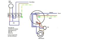
Wiring diagram for voltage regulator. 5 Wire Regulator Rectifier Wiring Diagram One of the most difficult automotive fix tasks that a mechanic or repair shop can consent is the wiring or rewiring of a cars electrical system. Here is a wiring diagram of the typical 5 wire cdi system on a lot of scooters comprising pick up input battery 12 volts in gnd and ignition coil out pins some common electrical setups and included the wiring diagrams.
2 yellow wires ac inputs white red dc output black yellow dc output and a brown wire. Cdi Wiring Diagram 5a236d6c634ce And Box Electrical Wiring Diagram Motorcycle Wiring Electrical Wiring 5 Pin 5 Wire Hk D Rectifier Voltage Regulator With Female Connector For 125cc 250cc Gy6 Qmb139 Scooter Engines Voltage Regulator 250cc Regulators. I replaced the voltage regulator aftermarket not Polaris and I thou Polaris had a 3-wire regulator-rectifier that was used on sleds with electric start.
16 hours agoRectifier Voltage Regulator For Mercury Mariner Outboard 5 Wire 815279-3 883072T Free 313427913770 Jun 07 2018 Mercury Outboard Wiring Diagrams Mastertech Marin. The color code remains the same. Normally the pins for USB1 and USB2 are in seperate rows.
How to wire a gy6 scooter regulator rectifier and how it all works part 3 the regulator duration. You either have the wrong regulator or a bad one. This is a image galleries about 5 wire rectifier wiring.
Motorcycle Regulator Rectifier Wiring Diagram Source. The article was submitted by mr. A combination regulator rectifier for.
Otherwise the arrangement will not work as it ought to be. Regulator rectifier diagram here you are at our site this is images about regulator rectifier diagram posted by maria nieto in wiring category on may 08 2019. In the 5-wire recreg the internal regulator shares the same hot lead from the rectifier that goes to the battery as.
Dave Absolutely Scooters. Each part should be placed and linked to different parts in particular way. May 11 2018 wiring diagram.
Panel where the rectifier are open causing high ripple or AC voltage while charging volts and amps are still. Connecting the rectifier Disconnect the 6-position 5 wire connector from the OE rectifier plug the. If you dont have a 5 wire hook-up try going with a 4 pin reg.
We ve even included standard wire colours where appropriate. 5 pin regulator rectifiier wiring diagramSana makatulong po ito sainyo mga broPara sa iba pang vidio wag nyo pong kalimutan magSUBSCRIBELIKE AND SHARETO GOD. There are 6 models of the CDI Rectifier Regulator to fit many of the Johnson Evinrude Mercury and Mariner outboards manufactured over the years going all the way back to the.
As stated earlier the lines at a Rectifier Regulator Wiring Diagram signifies wires. 4 wire voltage regulator wiring diagram. Put the Yellow and white diagonal from each other and the green and red diagonal from each other on the other 2 pins.
5 wire regulator rectifier wiring diagram 3 pin regulator rectifier wiring diagram 3 wire rectifier diagram kbpc5010 bridge rectifier wiring diagram how to wire stator and rectifier 12v rectifier regulator diagram motorcycle. Alternatively you can plug the connector onto the 4-pins row and leave the S-GND wire unconnected. Can a 6 wire rectifier be put on a bike with a 5 wire rectifier.
5 wire regulator rectifier wiring diagram. 3 phase 6 wire regulator rectifier wiring diagram. The best advice is not necessarily only look from the diagram yet understand how the components operate when in use.
2 from the alternator 1 fromto the battery positive 1 to ground Negative and another also to the battery. In the manner of grating to remove replace or repair the wiring in an automobile having an accurate and detailed 5 wire regulator rectifier. Studying the wiring diagram a bit more I can see that elec start sleds.
Your regulator has to match the stator you have. All the rectifiers on this page are rated at is rated at 55 amps constant use. Reddit gives you the best of the internet in one place.
For example on a 1981 Kawasaki KZ440 there are 5 wires going to the OE part. Regulator rectifier wiring diagram motorcycle voltage alternator troubleshooting zt 6605 6 wire generator tbolt usa tech database llc ky 5661 diode chinese diagr fl 8286 baja 90cc pit bike. Vacuum Diagram As Well 2001 Ford F 150 5 4 Vacuum Line Diagrams On size.
How to wire the 5 cables not in a row. It has 5 wires. But looking closely at the circuit diagram the green and reds both merge into a single wire shortly after the connector.
I replaced the voltage regulator aftermarket not polaris and i thou polaris had a 3 wire regulator rectifier that was used on sleds with electric start. 2 yellow wires ac inputs white red dc output black yellow dc output and a brown wire. Here is a wiring diagram of the typical 5-wire CDI system on a lot of scooters comprising pick-up input battery 12 volts in Gnd and Ignition coil out pinssome common electrical setups and included the wiring diagrams.

Voltage Regulator Rectifier Kohler Yesterday S Tractors Kohler Engines Electrical Diagram Voltage Regulator

Unique Wiring Diagram For Chinese 110cc Atv Wiring Diagram Chinese Atv Wiring Diagrams Roketa 11 Electrical Diagram Motorcycle Wiring Electrical Wiring Diagram

Onan Bf Ms 2425a Rectifier Wiring Help Mytractorforum Com The Friendliest Tractor Forum And Best Place For Tractor Information Onan Wire Case Tractors

Cdi Wiring Diagram Motorcycle Wiring Kill Switch Electrical Wiring Diagram

Lovely Wiring Diagram Alternator Diagrams Digramssample Diagramimages Wiringdiagramsample Wiringdi Electrical Circuit Diagram Voltage Regulator Alternator

Wire Harness Wiring Cdi Assembly For 50 70 90 110cc 125cc Atv Quad Coolster Go Kart Wish In 2022 Motorcycle Wiring 90cc Atv Chinese Scooters

16 Motorcycle Rectifier Circuit Diagram Motorcycle Wiring Voltage Regulator Circuit Diagram

15 Motorcycle Regulator Rectifier Wiring Diagram Motorcycle Diagram Wiringg Net Motos

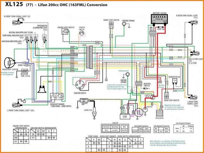
Chinese 125cc Engine Wiring Diagram And Tbolt Usa Tech Database Tbolt Usa Llc Motorcycle Wiring Pit Bike Bike Engine

Motorcycle Wiring Yamaha Yamaha Engines

50cc Scooter Wiring Diagram Chinese Atv Cdi Wiring Diagram Chinese Electrical Wiring Diagram Motorcycle Wiring Trailer Wiring Diagram

Engine Wiring Help Diy Go Kart Forum Motorcycle Wiring Diy Go Kart Go Kart

Wiring Diagram For 110cc 4 Wheeler Fresh 110 Atv Wiring Help Atv Electrical Diagram 150cc Chinese Scooters

Basic Wiring Diagram For All Garden Tractors Using A Stator And Battery Ignition System Ignition Coil Ignition System Kohler Engines

Pin By Sakkie On Hobbies Crafts Electronic Circuit Design Motorcycle Wiring Denso Alternator

Motorcycle Regulator Diagram And Amazon Wires V Voltage Regulator Rectifier 18 Motorcycle Regulator Diag Motorcycle Wiring Voltage Regulator Car Alternator
Filter Circuits With Capacitors Likewise On Kbpc5010 Bridge Rectifier Wiring Diagram

Yamaha Xs650 Wiring Schematic Xs650 Xs650 Bobber Yamaha

Let S See Some Chopped Wiring Diagrams Motorcycle Wiring Diy Go Kart Diagram