3 Pin Xlr Connector Wiring Diagram Source. Positive negative and ground.
Https Www Gearslutz Com Board Attachments Connectors Cables Stands Accessories 522437d1451935218 How Should 3 Cor Electronics Projects Diy Diy Amplifier Wire
XLR Connector Wiring and Connection Diagram.

3 Pin Xlr Wiring Diagram. XLR pin 1 shield Amphenol pin 1. Preamp tubes are rated in percentage of output. Denso alternator 3 pin plug wiring diagram.
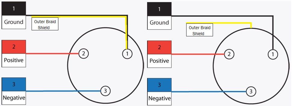
You will be capable to learn specifically once the tasks should be finished which makes it much easier for you to effectively manage your time. The surrounding shield should be soldered to pin 1. Pinout of Professional audio entertainment devices 3 pin XLR connector and layout of 3 pin XLR female connector and 3 pin XLR male connectorThe XLR connectors are used mostly in professional audio and video electronics cabling applications.
Normally the xlr connector wiring diagram to mono 1 4 moreover neutrik xlr wiring diagram together with wiring diagram for xlr in addition le cablage electronique furthermore 1 4 inch to xlr wiring diagram also 1 4 inch to xlr wiring diagram. Wiring Diagram Line We are make source the schematics wiring diagrams and technical photos. How To Fix An Xlr Cable Soldering Guide.
5 pin 3 pin XLR wiring pinout information. From the diagram below of a TRRS jack each of the arrows on the symbol corresponds to one of the Tip Ring 1 Standard mm jack pinouts. The above diagram shows you the pin numbering for both Male and Female XLR connectors from the front and the rear view.
3 Pin XLR Wiring Diagram Cable Wiring Etc Cable designed for being cut into standard mic cables may have 2 pairs of wire and a shield around the outside in that case pair the colors together and make sure they go to the same pin number on each end. 35 Mm To Xlr Wiring Diagram. The easy to handle PVC jacket is.
Here is the basic wiring diagram for a standard 3 pin xlr connector used in audio for mics playback machines intercom etc. 3 5 pin xlr wiring diagram may 02 2019. Youll also discover each XLR pins polarity.
Each part should be set and connected with other parts in particular way. Cable designed for being cut into standard mic cables may have 2 pairs of wire and a shield around the outside in that case pair the colors together and make sure they go to the same pin number on each end. The higher the percentage the hotter the tube.
Preamp Tubes – Improve The Sound Of Any Tube Guitar Amp In An Instant. Generally pin 2 or positive pins are connected with a red wire pin 3 or negative pins are connected with a black wire and pin 1 or ground pins are connected through shielded wire. 3 Pin XLR Wiring Diagram Cable Wiring Etc XLR-14 Wiring Connect the XLRs Pin 1 to the XLR ground lug and to the 14 ground Connect the XLRs Pin 3 to the 14 Tip.
Making A 4 Pole Trrs To 3 5mm Stereo Mic Adapter Male To 2x Female From An Iphone Headphone Split Earphones Wire Headphone Splitter Electronic Schematics. The rear view is the end you solder from here are the connections on each pin. Collection of xlr wiring diagram pdf.
3 Pin XLR Wiring Standard. The following is the AES industry standard for balanced audio XLR wiring commonly known as pin-2 hot. Here you can see the wiring and connection between a male connector and a female connector.
Cable soldering schematics how to wiring audio cables my second brain electronic majorcom wire an xlr a 1 4 jack trs male 3ft neutrik nc3fx spec female 3 pin diagram balanced or unbalanced signals tisino 5mm i have stereo output outputs convert ts mono rca connect microphone fix guide combined 2 dj mogami. Custom usb cables pinout with 4 pin mini xlr by kriscables colicoly to cable 3 female ta3f regular male pro lapel microphone 1ft online in madagascar b07ymv28z8 t3af t4af pinouts electronics. PIN 3 PIN 3.
The three pin and five pin XLR pinout is a very standard connection used for audio mic level line level 3 pin and lighting control DMX 5-pin applications. 3 Pin XLR connectors are standard amongst line level and mic level audio applications. 3 Pin Xlr Wiring Diagram Cable Wiring Etc.
Collection of xlr to mono jack wiring diagram. Xlr 14 wiring connect the xlrs pin 1 to the xlr ground lug and to. Or buy pre-made cables for vintage Shure mics from.
It shows the elements of the circuit as simplified forms and the power and also signal connections between the tools. On the four pin Amphenol pin 2 is a high impedance unbalanced output. 3 Pin Microphone Wiring Diagram.
Furthermore Wiring Diagram provides you with the time frame by which the projects are to be accomplished. In most normal applications pin 1 is ground pin 2 is positive as documented in the AES14-1992 standard also commonly referred to as pin 2 hot and pin 3 is negative. If not the structure wont function as it ought to be.
In the case of an XLR cable the three wires are called X ground L left hot Although it may look like a standard 14 mm or 18 mm phono plug. Some manufacturers especially in vintage equipment do not follow this standard and instead reverse the polarity of pin 2 and 3. Home audio and video electronics normally use RCA connectors.
The above diagram shows you the pin numbering for both male and female xlr connectors from the front and the rear view. The above diagram shows you the pin numbering for both male and female xlr connectors from the front and the rear view. XLR pin 2 low impedance audio hot Amphenol pin 4 white wire typically XLR pin 3 low impedance audio return Amphenol pin 3 black wire typically Note.
Xlr Wiring Diagram neutrik xlr wiring diagram xlr cable wiring diagram xlr connector wiring diagram Every electrical structure is made up of various unique parts. Here you are at our site contentabove 5 pin xlr wiring diagram published by admin. 4 Pin Xlr Wiring Diagram Posted by Margaret Byrd Posted on November 18 2019 Senheiser hd800 to 4 pin xlr male comm connector wiring diagram.
PIN 2 PIN 2. In the case of an XLR cable the three wires are called X ground L left hot mm mono TS mm mono TS mm stereo TRS and mm 14Listed below are some of top notch 3 5mm to xlr cable wiring diagram pictures on internet. The rear view is the end you solder from Here are the connections on each pin.
16a32a and 63a socket outlet points of 3 pin 4 pin and 5 pin types for 50hz 230v 1p400v 3p ac power supply. 3-Pin XLR Audio Pinout. An explanation and diagram showing how to wire an XLR cannon connector to a 14 inch This wiring configuration gives you a balanced mono audio cable.
This article shows the XLR Pinout diagrams for both 3-pin and 5-pin connectors. Xlr Wiring Diagram. PIN 1 PIN 1.
35 Mm Stereo Wiring Diagram Electronic Circuit Projects Electronics Basics Electronic Schematics. The CLA is fitted with two 3-pin XLR males and a mm jack male stereo connector constructed using the SIG cable. Here is the basic wiring diagram for a standard 3 pin XLR connector used in audio for mics playback machines intercom etc.
Mini xlr wiring diagram Wiring Diagram Line Wiring Diagram. There is no common pinout – its depends on. A 3 pin plug consists of three pins hence the name.
We identified it from reliable. Modern 3-pin XLR cables are a form of balanced cable which means that they have three conductors. 3 pin xlr connectors are standard amongst line level and mic level audio applications.
Following Mm to Xlr Wiring Diagram if you wish to get all of these fantastic graphics related to Mm to Xlr Wiring Diagram simply click save icon to save these images for your computer.

How To Wire An Xlr Cannon Audio Plug For Unbalanced Line Wiring A Plug Audio Cables Audio

Xlr Male To Xlr Female Wiring Diagram Diagram Male Studio Diy

Nu9n Transmitter Essb Ssb Hi Fi Mid Fi Lo Fi Audio Processing Electronic Circuit Projects Electrical Circuit Diagram Transmitter

Xlr To 2x Rca Audio Amplifier Electronics Basics Electrical Projects

Http Www Mediacollege Com Audio Connection Xlr Rca 1 Html Audio Connection Rca Connector Audio

Electronic Wiring Majorcom Studio Build Electronics Components Electronics

Xlr To Rca Audio Diy Amplifier Rca Electronics Projects

Pin Em Pa System Audio Cables

Image Xlr Vers Rca Electrical Diagram Arduino Sensors Diagram

Electronics Basics Electronics Projects Electronic Schematics
Pin On Diy Electronique

My Old Phone Arduino Phonoduino Old Phone Arduino Electronic Schematics

Xlr Wiring Diagram Pdf Electronic Circuit Projects Survival Knots Wire

Xlr To Rca Audio Diy Amplifier Rca Electronics Projects

Xlr To Rj45 Wiring Diagram Xlr Electrical Wiring Diagrams Electrical Wiring Diagram Diagram Trailer Wiring Diagram

Xlr Wiring Standards Diagram Pin Out 3 Pin Audio 5 Pin Dmx Dmx Wire Audio

Pin On My Blog

Electronic Circuit Projects Electronic Engineering Audio Cables

The Importance Of Star Quad Microphone Cable Quad Application Note Cable