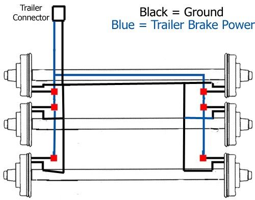
Sometimes the wires will cross. Short proof protected with a 4 brake capacity.
Complete Wiring For Lights Electric Brakes And Controller For A 94 Gmc 1 2 Ton Truck And Trailer Trailer Plans Trailer Wiring Diagram Trailer
BRAKE CONTROL 1Your Hopkins brake control can be mounted in any direction including upside down.

Brake Force Brake Controller Wiring Diagram. Ground the 7-way connector by screwing the white wire into the frame of the vehicle. Brake Force is Family owned and locally operated. WARNING Reversing BLACK and WHITE wires or improper wiring will damage or destroy brake control.
To install with a positive ground system use Tekonsha PN 3191 2. Brake controller installation starting from scratch etrailer com trailer control wiring diagram how to install a electric on tow vehicle troubleshooting installations. A brake controller is an electronic device mounted in your Dodge Rams cab that receives a signal from the brake light switch whenever you apply your foot to the brakes.
Brake force electric brake controller wiring diagram. Wiring a brake controller during installation typically involves 4 wires. See catalog for availability CURT part 51515 – male quick plug with pigtails CURT part 51500 – brake control wiring kit Key Features Display shows provides detailed brake force output.
If you set the sync power low it does not matter how hard you hit. Electric brake controller wiring diagram. Intuitive vertical manual slide matches the way a driver reaches for the control.
Brake force brake controller wiring diagram. Plug-in simple connection allows for quick installation and removal without cutting or splicing. Not recommended for use with BMW X5 Sport Utility Vehicles.
The 47225 brake control utilizes time based actuation for applying braking power to the trailer brakes. The brighter the glow the more braking force is being applied to the trailer brakes. If your vehicle is not equipped with a plug-and-play harness you can also splice in wiring for connecting a brake controller.
Injunction of two wires is generally indicated by black dot on the junction of two lines. Elecbrakes is designed to operate 1 to 2 braked axles. Electric Brake Controller Wiring Diagram.
Wiring Legend BLACK Wire Positive Battery WHITE Wire Negative Battery RED Wire cold side of stoplight switch BLUE Wire brake output to trailer 1. Connect wires coming from the plug-in simple harness with the corresponding wires coming from the brake controller. Installing a brake controller involves disconnecting the vehicle battery mounting the brake controller onto dash and plugging the unit in with a vehicle-specific wiring harness.
To test the driving functionality you will need to splice into the blue output wire of the brake controller and have your passenger monitor the output of the controller when driving. Brake Control Wiring Harness Chart OE HARNESS BRAKE CONTROL WIRE FUNCTION Chevrolet Red Black 12 Volts Light Blue Red Stoplight Black White Ground Dark Blue Blue Trailer Brakes Brown NA Illumination New Dodge Green Wire White w Red Tracer Black 12 Volts Blue w White Tracer Red Stoplight Green w Black Tracer White Ground Blue Blue Trailer Brakes Dodge. Solves the problem of inconvenient mounting out of reach controls and difficult to see displays.
WARNING Be sure to solidly connect all four wires or brake control will not function properly. Time based with a LED indicator that shows braking intensity. Elecbrakes is designed to operate 1 to 2 braked axles.
Auxiliary connection is optional it may be connected to any 12v to 24v constant power source or left unconnected. However it does not mean connection between the cables. If the unit is not adjusting the issue could be in the controller or in the way it was installed.
The black wire is the power supply line to the brake control. The brake control must be installed with a 12 volt negative ground system. A brake controller wiring installation kit makes light work.
Electric Brake Controller Wiring Diagram. Ive attached a wiring diagram to help further. Loosen and remove the nut located in the center of the box and remove cover Fig.
CAUTION Inadequate grounding may cause intermittent braking or lack of sufficient voltage to trailer brakes. It then sends a signal out through the trailer wiring coupler to engage the trailers electric brakes. On steep grades all G-Force sensors will sense inertia faster and more quickly.
The wiring installation utilizes the brake lights of the RV to activate the SMI system in combination with G-Force If the coach is equipped with an exhaust brake that illuminates the brake lights of the coach extra attention must be given to the activation light. Brake Force specializes in brakes vehicle maintenance and full service auto repair. To make wiring a brake controller easy and cost efficient we sell a brake controller wiring kit.
Can be mounted at any angle. Seperate components mount where you want them. The following diagram is a general guide for wiring common brake controllers into cars.
Accepts Tekonsha direct plugin wiring harness. Plug the connector into the second port in the top left hand corner of the junction box Fig. Electric Brake Controller Wiring Diagram.
Mainly found on Draw-Tite Brake Controllers it determines the amount of stopping force the brake controller puts out. Most states and provinces require a trailer brake controller based on the weight of the trailer. Please ensure you have the correct gauge wire and we do recommend you use an auto-electrician to wire the brake controller into your car.
The WHITE – wire must be connected to a known ground. Break away systems may be added to the service brake circuit. Before attaching these parts make wiring exposed by moving parts sharp edges or certain that the screws will not damage any compo hot components may.
Once you have chosen a location check behind the dash to be. Break away systems may be added to the service brake circuit. In this guide we cover step-by-step how to install a brake controller.
According to previous the lines in a Ford Trailer Brake Controller Wiring Diagram signifies wires. Our expert certified mechanics and technicians are ready to perform any repair or service you may need to help ensure your family is back safely on the road as quick as possible. An LED indicator will glow displaying braking intensity.
Hopkins Brake-Force trailer brake control combines simple installation with solid state dependability in a time-based easy-to-use controller. Brake control connection harness supplied with the tow vehicle if equipped CURT quick plug – custom connector for specific vehicles. Use a butt connector to connect the black wire in the duplex cable to the 12 volt hot lead black wire on the 7-way connector.
Wiring instructions for electronic brake controls p n 4399 rev k generic wiring diagram read this first. Make a small cut in the rubber sheath of the duplex cable and slightly separate the two wires inside. 325W x 55L x 15H.
Tekonsha P3 Brake Controller. To install with a positive ground system use tekonsha p n 3191 2. Auxiliary connection is optional it may be connected to any 12v to 24v constant power source or left unconnected.
Mount the bracket to a secure location with Phillips screws provided E where you will be able to view the display and easily access the vertical slide. Auxiliary connection is optional it may be connected to any 12v to 24v constant power source or left unconnected.

Car Brake System Diagram Trailer Light Wiring Car Brake System Diagram

Razor E500s Replacement Controller Electronicstudents Electricalstudents Engineer Razor Electric Scooter Electric Dirt Bike Electric Bike Diy

Trailer Brake Controller Information Tekonsha Trailer Wiring Diagram Brake

Trailer Brake Controller Information Etrailer Com Tekonsha Trailer Wiring Diagram Electrical Diagram

36 Volt Ez Go Golf Cart Wiring Diagram Sample Golf Cart Batteries Electrical Diagram Electric Golf Cart
Electric Brake Control Wiring Trailer Wiring Diagram Trailer Light Wiring Diagram

Trailer Wiring On Electric Trailer Brake Controller Wiring Trailer Light Wiring Trailer Wiring Diagram Boat Wiring

Electric Brake Controller Wiring Diagram Tekonsha Prodigy P3 Tekonsha Wire Electrical Problems

Trailer Breakaway Battery Wiring Diagram Trailer Wiring Diagram Trailer Light Wiring Diagram

Picture 5 Of 5 Trailer Wiring Diagram Deep Cycle Battery Ebay

Ez Go Golf Cart Wiring Diagrams Electric Golf Cart Ezgo Golf Cart Yamaha Golf Carts

Inspirational Hayes Brake Controller Wiring Diagram Diagram Trailer Wiring Diagram Wire

Building Tiny House On Flatbed Trailer And Need Brake Controller And Wiring For Electric Brakes Trailer Light Wiring Trailer Wiring Diagram Flatbed Trailer

Best Wiring Diagram Polaris E Bike For Controller Electric Bike Diy Razor Electric Scooter Electric Bike Kits

Building Tiny House On Flatbed Trailer And Need Brake Controller And Wiring For Electric Brakes Trailer Light Wiring Trailer Wiring Diagram Flatbed Trailer

E Bike Motor Wiring Diagram And Controller Electric Bike Diy Electric Scooter Electricity

220v 30a Wiring Diagram Help Page 2 Home Brew Forums Home Brewery Home Brewing Home Brewing Beer

48v 1800w Electric Brushless Speed Controller Motor Grip Fit Atv Go Kart Scooter Ebay Electric Scooter Electric Motor Electric Bike Diy

Perfect Western Snow Plow Wiring Diagram Image Collection Best Diagram Diagram Chart Thermostat Wiring