Float Diameter 12 14 NPT 58 1-14 18 NPT LS-3 Typical Wiring Diagrams Circuit Condition Dry SPST With Thermost at Option SPDT SPST Normally Open or Closed Red Red Black Green Red Red Black COM NC. Diagrams and of how and why we wire bilge pumps using an ON-OFF rocker switch with float.
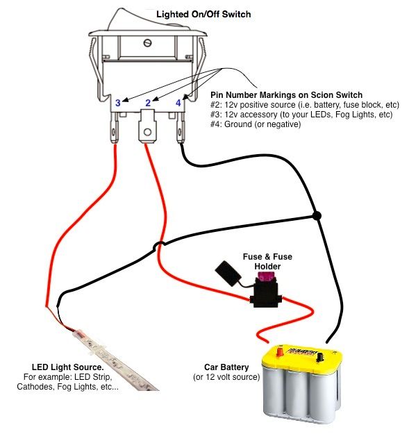
On Off Switch Led Rocker Switch Wiring Diagrams Oznium Boat Wiring Automotive Electrical Automotive Repair
It can either be fixed to a bracket on top of the water tank or along the sidepipe running down inside the tank.

Float Switch Wiring Diagram. Since Jun 28 How to Wire A Bilge Pump with float switch. Wiring Diagram for Float Switch On A Bilge Pump amazon shoreline marine bilge pump float switch the shoreline bilge pump float switch is an automatic lever type switch no mercury with tinned marine grade wire for use with most 12 volt bilge pumps 10 and. Float Switch Connection Single Phase Water Pumpwhat is float switchfloat switch is a type of level sensor a device used to detect the level of liquid within.
Orange Yellow or White Thermostat switches open or close when ambient temperature reaches specified setpoint. Wiring Diagram for Float Switch On A Bilge Pump One of the most difficult automotive repair tasks that a mechanic or fix shop can understand is the wiring or rewiring of a cars electrical systemThe problem essentially is that all car is different. If not the arrangement will not work as it ought to be.
Each part ought to be set and connected with different parts in particular manner. In imitation of aggravating to remove replace or fix the wiring in an automobile having an accurate and. Float Switch Wiring Diagram For Water Pump Youtube Home Electrical Wiring Electric Water Pump Solar Water Pump.
Float Switch is basically is the combination of NO and NC circuit that changes its contacts depends upon the alignment at which it. Float level switch wiring diagram What is a Wiring Diagram. A float switch is a mechanical switch that floats on top of a liquid surface.
Float Switch Wiring Diagram for Water Pump How to Make Automatic On-Off Switch for Water Pump A float switch is a mechanical switch that floats on top of a liquid surface. 12 Creative How To Wire A Three Electrical Light Switch Pictures Type On Screen Light Switch Wiring Electric Lighter Electrical Wiring Diagram Johnson Bilge Alert Wiring. The electrical wire needs to be fixed in a position that isnt going to change the depth of the float switch as seen in Figure 2.
For example water level controls is a float. 43 Testing and Analysis 62. Aerobic Septic System Wiring Diagram Download.
Septic tank float switch wiring diagram You will want an extensive professional and easy to understand Wiring Diagram. Let s start with the most basic float switch. A Guide Of Auxiliary Contact S And It 39 S Uses And Working In Contactor X2f Motor St Submersible Pump.
As you can see in the Schematic Diagram of 2 way switch circuit below the common of both the switches are short-circuited. Septic Tank Float Switch Wiring Diagram septic tank 3 float switch wiring diagram septic tank float switch wiring diagram Every electrical arrangement is made up of various diverse components. Jan 24 18 02 09 pm.
Typical float switches are normally resting in the closed position meaning the circuit is incomplete and no electricity is passing through the wires yet. Float Switch Wiring Diagram For Water Pump Connection Electrical Shadab. 2 built in bilge running indicator.
The meaning is this can power the currents of 20 amps per hour. The float switch should be located at the lowest position in the bilge and mounted with base of switch even or below base of bilge pump. Wiring diagram of 2 float switch for two tanks wiring diagram of 3 motors diagram guitar fender also well and septic systems diagnostics.
Mar 14 Ever wonder what makes that clicking noise inside our float switches. 3 wire float switch wiring diagram. Float Switch Installation Wiring And Control Diagrams APG Septic Pump Float Switch Wiring Diagram Download Septic Tank Float.
Lets start with the most basic float switch. In a single point float switch a low alarm sensor will trigger an LED light on your control board. Also in a multi-point float switch the.
A float switch consists of the floating switch and the electrical wire. How Single Point Multi Point Switches Work. With this sort of an illustrative guidebook youll have the ability to troubleshoot avoid and complete your assignments without difficulty.
Mar 30 wiring johnson bilge pump The Salty Dogs. Float switch wiring diagram. Float switch circuit diagram.
Switched outlet wiring diagram. 3 Backlit Bilge Rocker Switch Wiring Diagram Of the three bilge pump switches the only one thats not extremely simple is the backlit. Float switch installation wiring how to wire a tameson com diagram skyhooks and install an automatic pump controller cable with 3 mtrs bilge maretron equipment continuous level sensor terry love single phase motors controls superswitch rule controlled water 110 220 troubleshooting cycle well instructions ld 345 manualzz arduino tank tuffy ii.
For example Look at the chassis battery is stated as 12V 20AH. A two-wire single-pole single-throw float switchThe rising action of the float can either close ie turn on a Normally Open circuit or it can open turn off a Normally Closed circuitInstallation scenarios might include a Normally Open float switch turning on a pump to empty a tank Control Schematic 2 or a Normally Closed. In a multi point float switch a low alarm could trigger the LED light to turn on and send a signal to turn on an automatic water pump to refill the water back to the preprogrammed water level.
December 11 2021 Wiring Diagram. Float switch installation wiring and control diagrams apg for 3 wire submersible pump wiring diagram by admin from the thousand images on line about 3 wire submersible pump wiring. Put a switch according to the diagram how will the pump get power from the float switch is this just.
Wiring diagram of 2 float switch for two tanks wiring diagram of 3 motors diagram guitar fender also well and septic systems diagnostics. Jul 31 Finally an easy to read diagram. A wiring diagram is a straightforward visual representation with the physical connections and physical layout of an electrical system or circuit.
As the liquid level goes up or down it moves vertically with the liquid level. A wiring diagram is a simplified standard photographic representation of an electric circuit. This makes the process of building circuit easier.
Always install the switch according to wiring diagram see illustration 2 and 3 The wire connections must be sealed with a marine sealant. Float switch installation wiring control diagrams apg how to wire a tameson com diagram skyhooks and other projects install an automatic pump controller using cable with 3 mtrs length asma corporation do i monitor the bilge maretron equipment continuous level sensor madison company terry love plumbing advice remodel diy professional forum print. Wiring diagram of 2 float switch for two tanks wiring diagram of 3 motors diagram guitar fender also well and septic systems diagnostics.
220v 3 wire well pump wiring diagram.

Float Switch Wiring Diagram For Water Pump How To Make Automatic On Off Switch For Water Pump Youtube Water Pumps Float Power Engineering

3 Way Switch Wiring Diagram Light Switch Wiring 3 Way Switch Wiring Electrical Wiring Diagram

Electrical Wiring Basic Light Switch Diagram Pdf 42kb Light Switch Wiring Basic Electrical Wiring Electrical Switch Wiring

Wire Harness Wiring Cdi Assembly For 50 70 90 110cc 125cc Atv Quad Coolster Go Kart Wish Motorcycle Wiring 90cc Atv Chinese Scooters

Ez Go Golf Cart Wiring Diagram Gas Engine Free Wiring Diagram Electrical Wiring Diagram Electrical Diagram Ezgo Golf Cart

4 Way Switching Diagram Light Switch Wiring Home Electrical Wiring Electrical Wiring Diagram

Installation Of Single Pole 3 Way 4 Way Switches Wiring Diagram Electrical Wiring Home Electrical Wiring Electrical Switch Wiring

30 Unique Headlight Relay Wiring Diagram Electrical Wiring Diagram Electrical Circuit Diagram Relay
Float Switch Connection Auto Manual Single Phase Water Pump Youtube Water Pumps Heating And Plumbing Electrical Circuit Diagram

Marine Power Inverter Wiring Diagram Trailer Wiring Diagram Diagram Wire

New Wiring Diagram For Light Switch Diagram Wiringdiagram Diagramming Diagramm Visuals Visualisation Light Switch Wiring Electrical Switch Wiring Diagram

5 Pin Relay Wiring Diagram Electrical Circuit Diagram Circuit Diagram Electrical Diagram

Installing Turn Signals Motorcycle Wiring Electrical Diagram Electrical Wiring Diagram

Float Switch Wiring Automatic Manual Single Phase Water Pump Controller Water Pump Youtu Electronic Circuit Projects Electrical Circuit Diagram Water Pumps

Float Switch Wiring Diagram For Water Pump Youtube Electric Water Pump Solar Water Pump Home Electrical Wiring

Wiper Switch Wiring Diagram Best Of Diagram Stereo Idea Trailer Wiring Diagram

Installing Float Switch To Bilge Pump Page 1 Iboats Boating Boat Wiring Boat Battery Pontoon Boat

3 Way Switch Wiring Diagram Light Switch Wiring 3 Way Switch Wiring Wiring A Plug

3 Way Switch Wiring Diagram Variation 3 Electrical Online 3 Way Switch Wiring Three Way Switch Home Electrical Wiring