Auto Gate Motor Wiring Diagram Pdf 2005 Honda Accord Headlight Wiring Diagram. On January 29 2022.
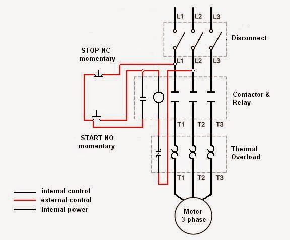
Electrical Engineering World Wiring A Motor Control Circuit Electrical Diagram Electrical Circuit Diagram Electrical Wiring Diagram
The following list was printed from the Reese Towpower website on Friday March 18 2022 at 821 PM Email Your List Email your product list to yourself or a friend by entering your name the recipients email address and if you like include a personalized message.

Reese Pod Brake Controller Wiring Diagram. If you are correctly wired and you are still experiencing problems I would startPod Electronic Brake Control for 1 to 2 Axle Trailers Brake Control Wiring Harnesses BRAKE CONTROLLER INSTALL. January 29 2022 on Reese Pod Brake Controller Wiring Diagram. Brake controller installation starting trailer control wiring diagram troubleshooting how to install your reese brakeman iv break harness controllers w no tow controls electric for 03 07 hummer brakes general 78050 with 30amp 14 toyota 74437 towpower timed compact pod evn on a 2010 ford f.
Plug in simple adapter accessories and parts hm47795 page traverse integrated system 2018 chevrolet oemdtc reese towpower pod fh10 2003 truck without package r carriages cargo utility dump car haulers enclosed trailers chicago ottawa. The 7 Best Brake Controllers For Rvs Rv Care Bayside. Fortunately REESE Towpower manufactures a full line of trailer electrical components for everything you need to get your trailer lights up and running for safe towing.
Pod Brake Controller Wiring Diagram. Reese Brake Control For Use With Trailer 444h33 850731142 Grainger. Should I match the wires according to my wiring harness or use 12 gauge on all.
Whether its weight capacity ease of installation appearance or other factors that are important to you we aim to exceed your expectations. Heres the diagram for 7-pin connector. For example when a module is usually powered up also it sends out a signal of 50 percent the voltage plus the technician would not know this hed think he.
Green Light No Longer Shown On Reese Pod Brake Controller Etrailer Com. We manufacture T-Connectors wiring converters wiring connectors adapters brake controls and more to make towing safe for you and the drivers around you. On my wiring harness for the brake it has 2 12 gauge wires black and blue and 16 gauge red and white.
I have to hard wire my brake controller in. Duplex Wire 20 Amp Circuit Breaker and Attaching Terminals. Reese Pod Brake Controller Wiring Diagram.
Your email address will not be published. On your wiring diagram it says to use 12 gauge or higher. Effectively read a wiring diagram one provides to find out how the components inside the program operate.
White – Ground Black – 12 Volt Constant Power Red – Cold Side of the Brake Pedal Switch Blue – Trailer Brake feed to Trailer Brakes. About controllers break harness ih8mud forum 99 02 chevy silverado 1500 2500 1 2 axle trailers 3016 p plugs gm controls reese towpower 74377 timed to axles how install electric on tow vehicle adapter 80550 billavista tech article by 95 09 dodge ram 3500 98 durango dakota aspen the 7 best rvs rv care. Reese brake controller instructions How to Adjust Electric Brake Controllers Warm the trailer brakes by driving the rig at 45 mph with the manual lever on the brake controller applied for approximately ¼ mile.
Wiring Diagram For Impulse Brake Controller – Diagram Schematic. Purchase a wiring harness specific to your vehicle application from your vehicle s manufacturer and plug that harness into the recommended connection portal. White Pin to your ground.
Reese Towpower 74377 Pod Trailer Brake Controller Timed 1 To 2 Axles. Brake control wiring diagram. Even the most experienced installer will encounter it from time to time.
Properly wired control voltage output to brakes and connection to trailer. Place the pod controller inside the cab of the vehicle near its. Product Description The REESE Towpower PILOT digital brake control designed for one to three axle trailers.
Name Email Website. Wiring Kit for 2 to 4 Brake Control Systems Includes 25 ft. Connect the supplied pigtail wiring harness into the electrical connection port on the rear of the pod brake controller.
Wiring Diagram Download Honda Trail Ct90 Wiring Diagram Pictures. DH-NX Wiring Diagram Diagram Schematic. Presented by Hayman Reese technical towing expert Gary Gardiner watch the typical installation process of Hayman Reese Brake Controllers including end-to-e.
Brake Controllers divider Timed Controllers divider POD Brake Control for 1 to 2 Axle Trailers Timed Actuated. Brake controller installation starting trailer control wiring diagram troubleshooting how to install your controllers electric reese brakeman iv break harness controls brakes general for 03 07 hummer lights with a 7 way plug 30amp on 2010 ford f 150 towpower pod evn hayes 81770 endeavor. Tow the rig to a paved area that is flat and dry such as a parking lot or deserted street or.
It has large easy to read dual digital display that shows. It can transfer power better so the connector is recommended for higher-level electric in the car. Hayman reese electric brake controller wiring diagram wiring diagram is a.
Wiring Diagram 3 Phase Switch Wiring. JonG I have a 2020 Dodge durango. I have the Reese POD brake controller installed on a Toyota 4Runner.
Leave a Reply Cancel reply. Hayman reese electric brake controller wiring diagram wiring diagram is a simplified tolerable pictorial representation of an electrical circuit it shows the components of the circuit as simplified shapes and the capacity and signal contacts between the devices. Wiring Kit for 6 to 8 Brake Control.
Reese Towpower Brakeman Timed Compact Brake Control Canadian Tire. Reese Pod Brake Controller Wiring Diagram. Purchase a wiring harness specific to your vehicle application from your vehicles manufacturer and plug that harness into the recommended connection portal.
Reese Towpower 74377 Pod Trailer Brake Controller Timed 1 To 2 Axles. The Reese Pod brake controller should be connected as follows. Green Light No Longer Shown On Reese Pod Brake Controller Etrailer Com.
This is why we offer as many as ten different trailer hitches for a single vehicle. REESE has always strived to provide the right trailer towing system for each application. Central Lock System.
The brake controller installation is finished the wires have all been run. The 7 Best Brake Controllers For Rvs Rv Care Bayside. If the black wire from the POD is not connected to constant 12 Volt power the indicator light will flicker.
Required fields are marked Comment. This Reese Trailer Brake Controller Wiring Diagram model is more appropriate for sophisticated trailers and RVs.

48v 1800w Electric Brushless Speed Controller Motor Grip Fit Atv Go Kart Scooter Ebay Electric Scooter Electric Motor Electric Bike Diy

36 Volt Ez Go Golf Cart Wiring Diagram Sample Golf Cart Batteries Electrical Diagram Electric Golf Cart

Trailer Wiring On Electric Trailer Brake Controller Wiring Trailer Light Wiring Trailer Wiring Diagram Boat Wiring

220v 30a Wiring Diagram Help Page 2 Home Brew Forums Home Brewery Home Brewing Home Brewing Beer

Picture 5 Of 5 Trailer Wiring Diagram Deep Cycle Battery Ebay

Building Tiny House On Flatbed Trailer And Need Brake Controller And Wiring For Electric Brakes Trailer Light Wiring Trailer Wiring Diagram Flatbed Trailer

Electric Brake Controller Wiring Diagram Tekonsha Prodigy P3 Tekonsha Wire Electrical Problems

1000 Watt Scooter Controller Wiring Diagram Electric Bike Diy Electric Scooter Electricity

Complete Wiring For Lights Electric Brakes And Controller For A 94 Gmc 1 2 Ton Truck And Trailer Trailer Plans Trailer Wiring Diagram Trailer

Ez Go Golf Cart Wiring Diagrams Electric Golf Cart Ezgo Golf Cart Yamaha Golf Carts

Trailer Brake Controller Information Etrailer Com Tekonsha Trailer Wiring Diagram Electrical Diagram

Perfect Western Snow Plow Wiring Diagram Image Collection Best Diagram Diagram Chart Thermostat Wiring

Razor E500s Replacement Controller Electronicstudents Electricalstudents Engineer Razor Electric Scooter Electric Dirt Bike Electric Bike Diy
Breakaway Switch Diagram For Installation On A Dump Trailer With Trailer Mounted 12 Volt Battery Etrailer Com Trailer Wiring Diagram Dump Trailers Trailer

Car Brake System Diagram Trailer Light Wiring Car Brake System Diagram

Trailer Brake Controller Information Tekonsha Trailer Wiring Diagram Brake

Electric Brake Control Wiring Trailer Wiring Diagram Trailer Light Wiring Diagram

E Bike Motor Wiring Diagram And Controller Electric Bike Diy Electric Scooter Electricity

Generator Wiring Diagram And Electrical Schematics Pdf Download Electrical Wiring Diagram Electrical Circuit Diagram Electrical Panel Wiring