A wiring diagram is a straightforward visual representation in the physical connections and physical layout of the electrical system or circuit. You will be in a position to learn precisely when the projects needs to be completed which makes it easier to suit your needs to properly control your time.
Wiring Diagram For 220 Volt Single Phase Motor Http Bookingritzcarlton Info Wiring Diagram For 2 Electrical Diagram Electrical Wiring Diagram Electric Motor
Wiring diagram book a1 15 b1 b2 16 18 b3 a2 b1 b3 15 supply voltage 16 18 l m h 2 levels b2 l1 f u 1 460 v f u 2.

3 Phase Motor Starter Wiring Diagram. 3 phase motor starter connection diagram. We need here three contactors an overload relay one auxiliary contact block a normally open start pushbutton a normally closed stop pushbutton a on delay timer of 0-20 second and a power supply with a fuse T3 T2 T3 OVERLOAD. 3 Phase Motor Starter Wiring Diagram Schematic Diagram 3 Phase Motors Wiring Diagram.
Line diagrams also called schematic or elementary dia-grams show the circuits which form the basic operation of the controller. A three phase motor must be wired based on the diagram on the faceplate. In this tutorial we will show the Star-Delta Y-Δ 3-phase induction AC Motor Starting Method by Automatic star-delta starter.
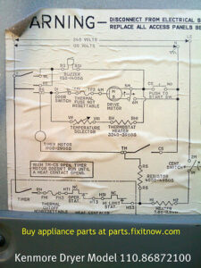
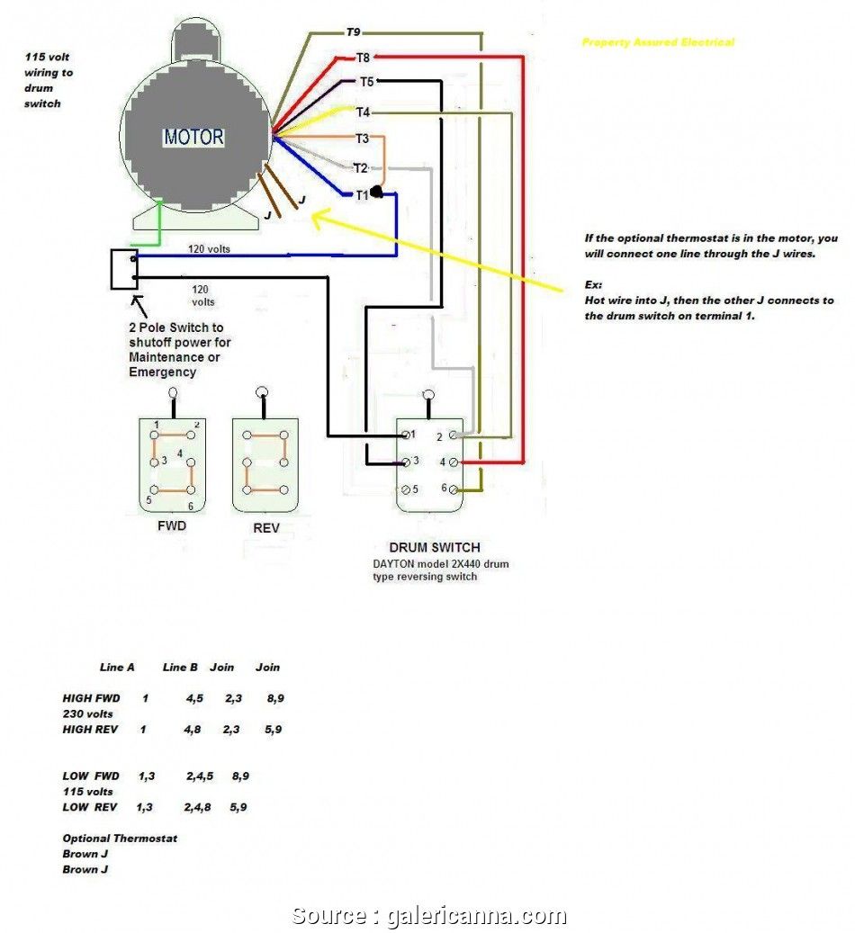
It has a Dayton motor with the following specs. Three Phase Motor Connection Schematic Power and Control Wiring Installation Diagrams. That being said there is a wide range of different motors and what you have on hand can be completely different.
Figure 1 typical wiring diagram. 3 phase motor wiring diagram pdf. In the United States for low voltage motors below 600v you can expect either 230v or 460v.
Star-Delta Y-Δ 3-phase Motor Starting Method by Automatic star-delta starter with Timer. 3 phase 480 volt motor wiring diagram basic for control 230v madcomics newbie 460v 12 wire three diagrams star delta starters explained the lead 480v us power oem water pump problems all motors untitled how to a baldor 13 neutral in vs six plug induction 1 5 hp 1kw 4. They do not indicate the physical relation-.
Siemens 3 Phase Motor Starter Wiring Diagram One of the most difficult automotive fix tasks that a mechanic or fix shop can put up with is the wiring or rewiring of a cars electrical system. A motor starter is a combination of devices used to start run and stop an AC induction motor based on commands from an operator or a controller. Star-Delta Y-Δ 3-phase Motor Starting Method by Automatic star-delta starter.
Is a typical wiring diagram for a three-phase mag-netic starter. In the united states for low voltage motors below 600v you can expect either 230v or 460v. It includes instructions and diagrams for various types of wiring methods as well as other items like lights home windows and so on.
In the united states for low voltage motors below 600v you can expect either 230v or 460v. Diagram dd6 diagram dd7 m 1 ln e diagram dd8 ln e l1 l2 l3 s c z1 u2 z2 u1 cap. In the 3 phase motor forward reverse starter wiring diagram.
The following diagram is shown for a 3-wire control of a delta-star connection. Contactor Wiring Guide For 3 Phase Motor With Circuit Breaker 3 Phase Motors Wiring Diagram Additionally Wiring Diagram gives you the time frame by which the projects are for being finished. A three-phase motor must be wired based on the diagram on the faceplate.
Time-lapse of schematic diagram drawn into a wire diagram and the wiring of the magnetic motor starterMotor Wiring at. Wiring Diagram contains several in depth illustrations that present the relationship of various things. D Wye-delta open transition 3-phase motors.
Magnetic starter 3 phase motor dol china magentic made in com franklin electric e tech substart3p three direct online wiring diagram working principle electrical4u star connection earth bondhon types contactor plc control how do i connect a on line to single schneider uk through and why. Three Phase Motor Connection STARDELTA Without Timer Power Control Diagrams. Wiring diagram comes with numerous easy to follow wiring diagram directions.
Square D Motor Starters Wiring Diagram sq-d motor starter wiring diagram square d 3 phase motor starter wiring diagram square d 8536 motor starter wiring diagram Every electric structure is composed of various distinct pieces. Wiring Diagrams ww introduction. The misery in reality is that all car is different.
The first step is to figure out the voltage of your phases. It consists of directions and diagrams for different varieties of wiring methods along with other things like lights windows and so forth. Siemens 3 Phase Motor Starter Wiring Diagram.
3 Phase 2 Phase 3 Wire Two-Speed Starter Bulletin 609TS Sizes 0 1 3 Phase 2 Phase 3 Wire For separate winding motors only WIRING DIAGRAMS w Bulletin 609U The Bulletins 609U and 609TU are the same as the standard Bulletin 609 Manual Starters except for the addition of Under- voltage Protection. Weg Electric Motor Wiring Diagram Wiring Diagram 3 Phase Motor Starter Wiring Diagram Pdf. Three Phase Motor Connection StarDelta Y-Δ Reverse Forward with Timer Power Control Diagram.
September 6 2019 by faceitsalon. 3 phase air compressor motor starter wiring diagram. Several other combinations are possible in North America and other.
A wiring diagram is a simplified traditional photographic representation of an electric circuit. Star delta starter explained in plain 3 phase induction motor connect a three power circuit for what is theory and laboratory manual schematic diagram of how to. If not the structure wont work as it ought to be.
Star delta y δ 3 phase motor starting method by automatic star delta starter with timer. Collection of 3 phase motor starter wiring diagram youll be able to download free of charge. Model 3N085 3 HP 3 Phase 3495 RPM motor.
3 Phase Induction Motor Star Delta Connection Diagram Wiring Diagram Line Wiring Diagram. Typical Wiring Diagram Line diagrams show circuits of the operation of the controller. For instance if a module is usually powered up and it sends out a new signal of half the voltage and the technician will not.
Although these systems may seem intimidating at first a walkthrough on 3 phase wiring for dummies will help clarify the whole situation. How to wire up a 3 phase motor starter – Diagram Schematic. In the manner of exasperating to remove replace or fix the wiring in an automobile having an accurate and.
3 Phase Motor Starter Wiring Diagram Gallery. Please download these 3 phase motor starter wiring diagram by using the download button or right select selected image then use Save Image menu. 3 phase star delta motor.
A wiring diagram is a simplified conventional pictorial representation of an electric circuit. Magnetic Starter Wiring Diagram For 220 Wiring Diagram 3 Phase Motor Starter Wiring Diagram. Motor Starters are types switches either electromechanical or solid state that are designed to start and stop the motors by providing the necessary power to the.
T1 and T3 to motor. Each part should be placed and linked to different parts in specific way. 3 Phase Induction Motor Star Delta Connection Diagram Wiring Diagram Line Wiring Diagram.
If you have a 120V coil instead of running a line from Coil Overload L2 you must run Coil Overload Neutral. In North America an induction motor will typically operate at 230V or 460V 3-phase 60 Hz and has a control voltage of 115 VAC or 24 VDC. To properly read a electrical wiring diagram one offers to learn how the particular components in the system operate.
Below is the motor data plate and whats left of the wiring diagram. To use three-phase electricity a motor needs windings spaced 120 degrees apart. Wiring Diagram consists of numerous detailed illustrations that display the relationship of varied things.
It reveals the elements of the circuit as streamlined forms and the power and signal connections between the tools. 2 contactors burned out in one day but nothing wrong with motor.

Pin On Starter Wiring

Starter Motor Starting System How It Works Problems Testing Starter Motor Motorcycle Wiring Automotive Repair

Best Relay Wiring Diagram 5 Pin Bosch Electrical Circuit Diagram Circuit Diagram Electrical Diagram

45 Unique Reversing Motor Starter Wiring Diagram Electrical Circuit Diagram Circuit Diagram Electrical Symbols

3 Phase Motor Wiring Diagrams Home Electrical Wiring Electrical Installation Diy Electrical

Weg Motor Capacitor Wiring Diagrams Schematics And Baldor Diagram In Electric Motor Electrical Wiring Diagram Motor

60 Beautiful Motor Starter Wiring Diagram Electrical Circuit Diagram Circuit Diagram Electrical Wiring Diagram

Single Phase Motor With Capacitor Forward And Reverse Wiring Diagram Circuit Diagram Electrical Circuit Diagram Electrical Diagram

70 Luxury Single Phase Dol Starter Wiring Diagram Electrical Wiring Diagram Electrical Circuit Diagram Circuit Diagram

Push Button Ignition Switch Wiring Diagram New Boat Wiring Kill Switch Electrical Wiring Diagram

How To Wire Contactor And Overload Relay Contactor Wiring Diagram Electrical Online 4u Electrical Circuit Diagram Diagram Electrical Wiring Diagram

3 Phase Contactor Wiring Diagram Pdf Home Electrical Wiring Electrical Circuit Diagram Electrical Wiring Diagram

3 Phase Split Ac Wiring Diagram Ac Wiring Air Compressor Pressure Switch Split Ac

Contactor Wiring Guide For 3 Phase Motor With Circuit Breaker Overload Relay Nc No Switc Electrical Wiring Diagram Circuit Diagram Electrical Circuit Diagram

3 Phase Start Stop Wiring Diagram Circuit Diagram Electrical Circuit Diagram Electrical Diagram

Square D Motor Control Center Wiring Diagram Well Pump Pressure Switch Diagram Wire

30 Unique Motor Starter Wiring Diagram Start Stop Your Starter Went Out And You Wan Basic Electrical Wiring Electrical Panel Wiring Electrical Circuit Diagram

Wiring Diagram For Motor Starter 3 Phase Controller Failure Relay Electrical Pleasing Thre Electrical Wiring Electrical Circuit Diagram Electrical Panel Wiring

3 Phase Motor Wiring Diagrams Non Stop Engineering Electrical Circuit Diagram Electrical Diagram Electrical Wiring Colours