Afcs wiring diagram list the proper phase voltage and amp load. Check rotation of fans exhaust fans will move some air in reverse see rotation arrow on fan.

Awesome Three Wire Alternator Wiring Diagram Gm Diagrams Digramssample Diagramimages Wiringdiagramsample Wiringdiagram Diagram Alternator Wire
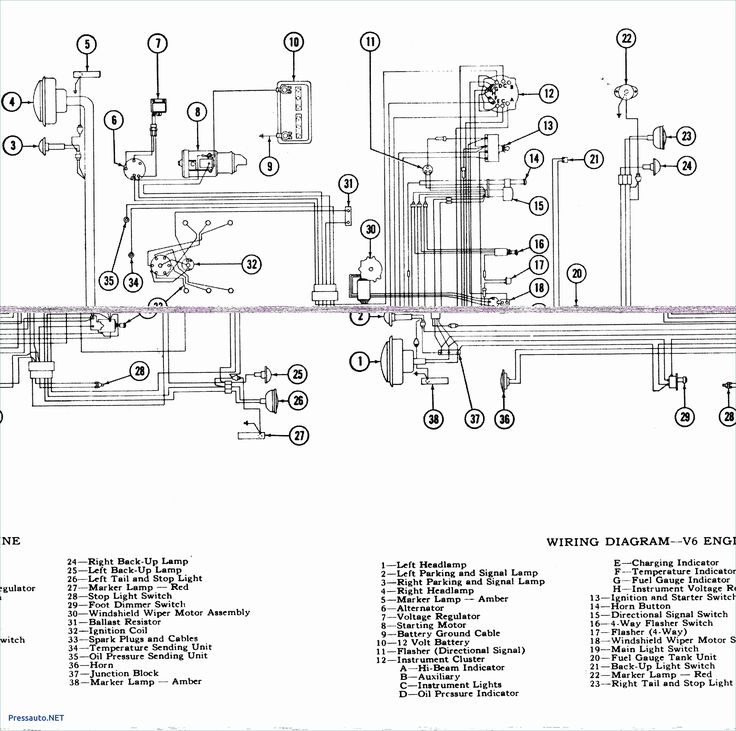
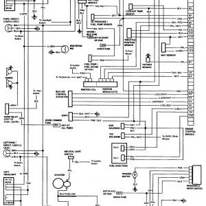
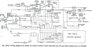
It reveals the elements of the circuit as simplified forms and the power as well as signal links between the gadgets.

Exhaust fan interlock wiring diagram. Verify input power voltage before connecting to starters or contactors. A wiring diagram is a simplified conventional photographic representation of an electric circuit. To correct rotation of fans reverse any two leads from the 3 phase starter to the fan.
Two different diagrams are shown. Energy management system network wiring schematic general and isolation exhaust fan control vfd hand off respective ahu interlock h o status ct ol s di 120v from transformer in starter p l. Collection of exhaust fan wiring diagram.
Diagram a is the more general case in which lights l 1 l 2 and the fan are all powered by separate power sourcres. Ef 1 ief 2 to have dual fan with the second fan to be used as a back up. 3ø wiring diagrams 1ø wiring diagrams diagram er9 m 3 1 5 9 3 7 11 low speed high speed u1 v1 w1 w2 u2 v2 tk tk thermal overloads two speed star delta motor switch m 3 0 10v 20v 415v ac 4 20ma outp uts diagram ic2 m 1 240v ac 0 10v outp ut diagram ic3 m 1 0 10v 4 20ma 240v ac outp uts these diagrams are current at the time of publication.
Diagram b is for the case where electrical power is common for all the lights and the fan from the same source.

How To Wire A Motor Starter 2013 Issue 5 2005 Library Electrical Circuit Diagram Electronic Engineering Electrical Wiring Diagram

Plc Implementation Of Forward Reverse Motor Circuit With Interlocking Eep Electrical Circuit Diagram Circuit Electrical Diagram

Bsi 012 Balancing Act Exhaust Only Ventilation Does Not Work Building Science Corporation Ventilation Exhausted Acting

Half Manual Power Window Wiring Diagram Electrical Circuit Diagram Car Mechanic Electrical Diagram

Star Delta Starter Y D Starter Power Control Wiring Diagram Circuit Diagram Electrical Circuit Diagram Delta Connection

Trane Air Handler Wiring Diagram Wiring Diagram Lambdarepos Intended For Trane Wiring Diagram Heat Pump Coding Diagram Design

Split Air Conditioner Wiring Diagram In 2020 Thermostat Wiring Electrical Wiring Diagram Electrical Diagram

Wiring Diagram Vw Beetle Sedan And Convertible 1961 1965 Vw Super Beetle Carro Fusca Fusca 62

Exhaust Fan Interlock Wiring Diagram

Diagrama De Cableado De Un Generador Portatil Al Hogar Manual Del Interruptor De Transferencia Del In 2020 Transfer Switch Portable Generator Generator Transfer Switch

Plc Timer Program Ladder Logic Plc Programming Timer

Diagram Exhaust Fan Interlock Wiring Diagram Full Version Hd Quality Wiring Diagram Love And Monsters Diagrams Pachuka It

Connecting A Timed Fan Unit How To Wire A Bathroom Extractor Fan With Timer Bathroom Extractor Bathroom Sink Diy Home Electrical Wiring

Electrical Wiring Diagrams For Air Conditioning Systems Part Two Electrical Knowhow Electrical Wiring Diagram Hvac Air Conditioning Air Compressor Motor

Wiring Diagrams For A Ceiling Fan And Light Kit Do It Yourself Help Com Bathroom Fan Light Home Electrical Wiring Diy Electrical

Simple Basic Led Circuit Simple Electric Circuit Circuit Diagram Electronics Basics

A Plc Has Been Programming To Control The Starting And Stopping Of A Three Phase Electric Motor The Program Plc Programming Ladder Logic Electronic Schematics

16 Ao Smith Electric Water Heater Wiring Diagram Water Heater Thermostat Electric Water Heater Water Heater Repair


