In some quarters the term 220 volt has become synonymous with 240 volt which in most countries has become the dominant standard just as 120 volt circuits have replaced 110 volt models if your home electricity was put in before 1980 you may have. Connect the two top terminals on the switch to the l1 and l2 connections in the motor s electrical enclosure.
How To Wire An Electric Motor To Run On Both 110 And 220 Volts Hunker Electric Motor Electricity Circuit Bending
Power voltage x current with current measured in amps.

220 wiring diagram. Wiring 220 volt electrical outlet. Each of the two top terminals represents one of the opposite poles of the 220 volt power circuit as do the two bottom terminals. See how electrical outlets for the home are wired.
Never rely on a wire s color alone. Each one is 110 volts. The equation is as follows.
The 220 volt circuits as they were known prior to the 1960s are now commonly known as 240 volt circuits and 110 volt circuits are now 120 volt circuits. Wiring 220 volt boxes and motors is serious business. Some powerful appliances require extra juice so they need 220 volt lines and outlets which draw electricity from 220 volt electric panels.
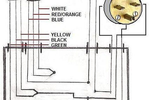
Thus to achieve 900 watts of power 4 1 amps would be required with 220v wiring whereas approximately 8 2 amps would be required with 110v wiring. Of course used for a clothes dryer. 220 volts 30 amps wire connections for x y w 240 volt receptacle dryer outlets the black wire attaches to outlet terminal x the red wire attaches to outlet terminal y the white neutral or green wire or ground wire attaches to outlet terminal w commonly known as a dryer outlet.
However working on your circuit breaker box and electrical system can lead to serious injury or death if you don t know what you re doing so hire an electrician if you don. When 220v wiring is used less current is required than with 110v wiring. In the below diagram you will notice that for a 220 volt outlet you would need a two pole breaker.
Combined you have your 220 volts. Home electrical wiring includes 110 volt outlets and 220 volt outlets and receptacles which are common place in every home. Wiring a new 220 outlet is a project that someone who has experience working with electricity can do safely by working carefully and following the proper precautions.
Here is a picture gallery about 3 wire 220v wiring diagram complete with the description of the image please find the image you need. Depending on where you live the branch circuit wiring in your home will be made with individual conductors run through a hollow metal conduit or with one of three types of cable. For more information about 220 volt wiring diagram 220 volt wiring diagram.
Wiring residential homes with 240 volts is a necessity for powering some heating and cooling equipment as well as some large appliances. What this means is that the breaker will take the power from the panel by the two very different phases. How to wire 240 volt outlets and plugs within 3 wire 220v wiring diagram image size 750 x 328 px and to view image details please click the image.
Plastic sheathed or type nm. Power is measured in watts. A cable is a factory made assembly of conductors in an outer jacket or sheath.

220 Volt Gfci Breaker Wiring Diagram Gfci Breakers Wire

Wiring Diagram For 220 Volt Air Compressor Bookingritzcarlton Info Electrical Wiring House Wiring Electricity

Wiring Diagram For 220 Volt Single Phase Motor Bookingritzcarlton Info In 2020 Electricity Diagram Electric Motor

Wiring Diagram For 220 Volt Single Phase Motor Bookingritzcarlton Info In 2020 Electrical Wiring Diagram Electric Motor Electrical Diagram

Wiring Diagram For 220 Volt Submersible Pump Http Bookingritzcarlton Info Wiring Diagram For 220 Volt Sub Submersible Pump Submersible Submersible Well Pump

Unique Wiring Diagram 220v 3 Wire Outlet 3 Wire 220v Wiring Dryer Outlet Outlet Wiring Diy Electrical

Wiring Diagrams For Electrical Receptacle Outlets Electrical Wiring Outlet Wiring Home Electrical Wiring

Wiring Diagram For 220 Volt Single Phase Motor Bookingritzcarlton Info In 2020 Electrical Diagram Electric Motor Stepper Motor

Wiring Diagram For 220 Volt Dryer Outlet Bookingritzcarlton Info In 2020 Dryer Outlet Electric Dryers Outlet Wiring

Circuit Breaker Wiring Diagrams Do It Yourself Help Com Electrical Wiring Home Electrical Wiring Electricity

Wiring Diagram 220 Volt Service Gfci Hot Tub Delivery Home Electrical Wiring

Electrical Wiring 220 Volt Switch Wiring Diagram Jack With A Light 97 Similar Jack With A L Light Switch Wiring Baseboard Heater Thermostat Thermostat Wiring

Wire A Dryer Outlet Dryer Outlet Diy Electrical Electrical Wiring

Wiring Diagram For 220 Volt Submersible Pump Http Bookingritzcarlton Info Wiring Diagram For 220 Volt S Well Pump Well Pump Pressure Switch Submersible Pump

Wiring Diagram For 220 Volt Generator Plug Bookingritzcarlton Info In 2020 Electrical Panel Wiring Outlet Wiring Electricity

220v Welder Plug Electrical Plug Wiring Outlet Wiring Ac Plug

Wiring Diagram For 220 Volt Dryer Outlet Bookingritzcarlton Info In 2020 Dryer Outlet Outlet Wiring Dryer Plug

Wiring Diagram For 220 Volt Generator Plug Bookingritzcarlton Info In 2020 Outlet Wiring Ac Plug Trailer Wiring Diagram

Wiring Diagram For A 30 Amp 240 Volt Circuit Breaker Home Electrical Wiring Electrical Wiring Electrical Wiring Outlets