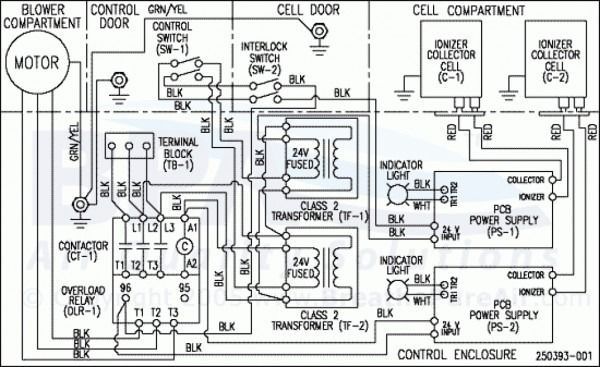
In general a class 2 circuit operating at 24v with a power supply durably marked class 2 and not exceeding 100va is the type most commonly used. Primary voltage1 secondary volts va class 2 transformers 590 120v ac 10v ac 5 590y 240v.
Industrial Wiring Diagram Helloo
The nec is the source of the class 2 circuit definition as well as for the class 2 power supply definition.

Class 2 transformer wiring diagram. Class 905097 transformer disconnects98 class 907098 enclosure selection guide99 conductor ampacity and conduit tables100 101 wire data102 electrical formulas103 104 list of tables table 1 standard elementary diagram symbols 1 table 2 nema and iec terminal markings 4 table 3 nema and iec controller markings and elementary diagrams 4. Class 2 defines the portion of the wiring system between the load side of a class 2 power supply beginning from the outside of a cabinet or machine and the connected equipment. Transformers ac class 2 590 series features and specifications non regenerative thermal overload protection grounding wire pre stripped primary side pigtails screw terminal connections on secondary ordering information description cat.
Edwards series class 2 signaling. For in wall wiring applications use 18 22 awg 2 conductor cable class 2 or higher commonly sold as in wall speaker or thermostat wire. Wiring diagram weight lbs c rise full capacity tapsa a fcbn full capacity taps below normal where noted.
The low voltage in this button and wiring configuration is generated by a class 2 120 volt transformer located somewhere within your home. Edwards series class 2 signaling transformers are easy to install low voltage the y transformers are for commercial and residential use. 120 volts enters the primary side of this small transformer and then based on the number of copper coils on the secondary side a voltage of somewhere between 16 24 volts exits the transformer.
Transformers are easy to install low voltage power sources for the y transformers are for commercial and. This will give you more room to tie transformer and dimmer wiring together. Typical class 2 circuits include air conditioning thermostats garage door openers and sprinkler system controls.
Route the ac wires from transformer through rigid spacer to the open box extender. The nec defines a class 2 circuit as that portion of the wiring system between the load side of a class 2 power source and the connected equipment. A class 2 circuit consists of the electrical components and wiring between the power source and the equipment being driven.
480 v delta primary to 208y 120 v secondary 60 hz 3 3t2f 12c 4 on page 17 125 115 2 5 fcbn 6 6t2f 12c 150 115 2 5 fcbn 9 9t2f 14c 265 115 2 5 fcbn 15 15t2f 14c 335 115 2 5 fcbn 30 30t2f 16c 8 on page 17 775 115 2 5 fcbn. Transformer to screw terminals. Edwards transformer vac 24vac 20 va signaling doorbell.
These are low current applications operating at 100va or less and 30 volts or less. Due to its power.

How Amps Work Amplifier Circuit Diagram Tube

2n3055 Amplifier Circuit Diagram Audio Amplifier Circuit Diagram Amplifier

Measurement Circuits Page 23 Circuit Wiring Diagrams

Doorbell Wiring Diagrams Diy House Help Doorbell Home Electrical Wiring Diagram

0 24 Volt 2 Amp Bench Top Power Supply Make Power Supply Analog Circuits Power

2n3055 Amplifier Circuit Diagram Audio Amplifier Amplifier Circuit Diagram

Electrical Wiring Diagrams For Air Conditioning Systems Part Two Electrical Knowhow Electrical Wiring Diagram Hvac Air Conditioning Air Compressor Motor

Audio Output Transformer Wiring Diagram Bookingritzcarlton Info Transformers Auto Transformer Diagram

Power Supply 1 Trafo 2 Kiprok Bridge Skema Kelebihan Dan Peruntukannya Rangkaian Elektronik Teknik Listrik Elektronik

Audio Output Transformer Wiring Diagram Bookingritzcarlton Info Transformers Transformer Wiring Old Radios

Woodworking 12012 Centre Tapped Transformer Wiring Specifications How To Use It Electronic Circuit Projects Transformer Wiring Electronics Mini Projects

Top261 Amplifier Power Supply Class D Smps Top261 Schematic Switch Mode Power Supply Circuit Power Supply Circuit Power Supply Switched Mode Power Supply

Power Supply And Wiring System For Consumer Mains House Wiring Electronic Schematics Home Electrical Wiring

Switching Mode Power Supply 10a 20 50v Dc Ct Electronic Circuit Power Supply Circuit Switched Mode Power Supply Circuit Diagram
View Source Image Electrical Transformers Transformer Wiring Transformers

How To Make Inverter 12v Dc To 220v Ac Electronic Circuit Design Circuit Diagram Electrical Circuit Diagram

Audio Output Transformer Wiring Diagram Http Bookingritzcarlton Info Audio Output Transformer Wiring Diagram Amplifier Power Amplifiers Audio

Audio Output Transformer Wiring Diagram Bookingritzcarlton Info Electrical Circuit Diagram Circuit Diagram Isolation Transformer

24 Volt Transformer Wiring Diagram With Nfz 5 2 Gif Transformer Wiring Diagram Transformers