480 to 120 240 transformer wiring 06 04 2019 06 04 2019 2 comments on 480 to 120 240 transformer wiring a volt primary transformer with a volt secondary is operated at volts regardless of whether the source is three phase 3 wire or three phase 4 wire. 17 lovely graphs 480 to 120 240 transformer wiring.
480v 120v Transformer Wiring Diagram 3 Phase Step Down Bright With And 480v Transformer Wiring Light Switch Wiring 3 Phase Transformer
480 volt to 120 transformer 480v step down up 208 isolation 240v.

480v to 120v control transformer wiring diagram. As discussed earlier in this booklet if wire c is supplied on the starter magnet coil voltages greater than 120v you must remove it. The schematic symbol for the transformer is represented by two groups the main motor circuit operates at v while the control circuit is at v. Control circuit wiring of cpts.
Variety of step down transformer 480v to 120v wiring diagram. 240 x 480 secondary. A wiring diagram is a streamlined traditional pictorial representation of an electrical circuit.
480v to 120v transformer wiring diagram elegant 3 phase step down phase wiring diagram in addition 480v step down transformer wiring. Click on the image to enlarge and then save it to your computer by right clicking on the image. Assortment of 480v to 240v transformer wiring diagram.
Figure 4 control power transformer wiring diagram. 480v to 240v transformer wiring diagram 240v to 480v step up transformer wiring diagram 480v 3 phase to 240v single phase transformer wiring diagram 480v to 240v 3 phase transformer wiring diagram every electric arrangement is composed of various unique components. 480 volt to 120 volt transformer wiring diagram sample 480 to 120 transformer wiring diagram wiring data.
None x4x1 h4 h3 h2 h1 x2x3 primary. A wiring diagram is a simplified conventional pictorial representation of an electrical circuit. 14 01 2019 14 01 2019 3 comments on 480v to 120v control transformer wiring diagram why use a control power transformer.
120 240 2 2 1 2 anfc 4 2 2 bnfc x4 x1 h10 h2 h3. Collection of 480 volt to 120 volt transformer wiring diagram. Remove wire c if supplied from starter s control circuit.
480v to 120v transformer wiring diagram wiring diagram. This will convert the starter from common control to separate control. 240 x 480 secondary.
Each component should be placed and connected with different parts in particular manner. It reveals the elements of the circuit as streamlined shapes as well as the power and also signal connections between the gadgets.

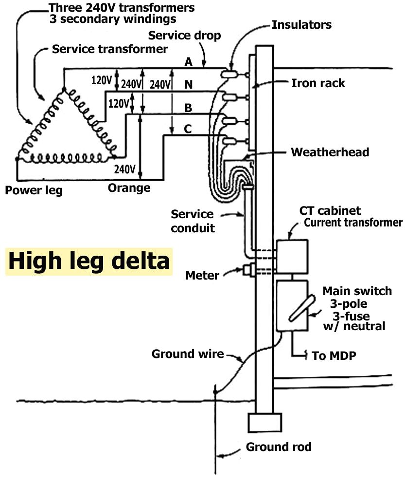
High Leg Delta Electrical Engineering Books Power Engineering Electrical Projects

Two Speeds Two Directions Multispeed 3 Phase Motor Power Control Diagrams Electrical Technology Electrical Circuit Diagram Power Directions

480v Ac Control 3 Phase Ssr Dc To Ac Three Phase Solid State Relay Control Relay Power

Solar Power System Wiring Diagram Electrical Engineering Blog Solar Solar Projects Solar Heating
5 Transformer Constructions You Re Most Likely To See Inside Buildings Eep Transformer Construction Electrical Projects Transformer Wiring

Simbolo Contactor Esquema Unifilar Google Search Simbologia Electrica Simbologia Simbolos

Understanding The Basics Of Wye Transformer Calculations Basics Content From Electrical Construction M Transformers Understanding Generator Transfer Switch

King Electric 5700 Watt 240 Volt Single Phase Paw Garage Portable Heater With Built In Thermostat Kbp2406 The Home Depot In 2020 Garage Heater Portable Heater Shop Heater

Ssr 25va Ac 24 380v Adjustable High Voltage Solid State Relay 25a Single Phase Voltage Regulator Free Potentiometer 1p High Voltage Relay Voltage Regulator

Borneras Motor Estrella Triangulo Esquemas Electricos Esquemas Electricos Electricidad Industrial Diagrama De Circuito Electrico

Grounding For Control Transformers Technical Articles In 2020 Transformers Circuit Design Isolation Transformer

Color Code For Residential Wire How To Match Wire Size And House Wiring Electrical Wiring Electricity

Module Cm1200ha 34h Affiliate Transistors Electrical Equipment Electricity

Diagrams Digramssample Diagramimages Dslr Nikon

Resultado De Imagen Para Conexion Estrella Delta Transformadores Secundario 480v Electrical Projects Electrical Wiring Electrical Transformers

Running A Three Phase 480 Volt Motor On Single Phase 120 Volt Diy Electronics Motor Wire

Los Motores De 6 Terminales Son Disenados Para Trabajar En 2 Tensiones Conexion Triangulo Delta Para Un Vo Motor Electrico Motores Proyectos Electricos

Basics Of Distribution Substations For Electrical Engineers Beginners Electrical Engineering Electricity Engineering

How To Build An Auto Start Rotary Three Phase Converter Electrical Projects Electrical Shop