3-Phase Transformer Wiring Diagram. 120/240 2, 2 1/2% anfc, 4, 2 /2% bnfc x4 x1 h10 h2 h3 3 phase step up transformer 240 to 480 wiring diagram wiring diagram is a simplified pleasing pictorial representation of an electrical. • the wiring diagram in figure 3a can be made implemented using a bank (group) of three single phase (1φ) transformers.
3 Phase 480 To 240 Transformer Wiring Diagram Easy Wiring from easywiring.info
The primary and secondary windings of a transformer can be connected in different configuration as shown to meet practically any requirement. 120/240 2, 2 1/2% anfc, 4, 2 /2% bnfc x4 x1 h10 h2 h3 3 phase step up transformer 240 to 480 wiring diagram wiring diagram is a simplified pleasing pictorial representation of an electrical. In either case, the windings may be connected in four different connection methods.
Phase Three Single Transformers Wye Electrical Alternator Connected Engineering Delta Words Few Power Wire Winding.
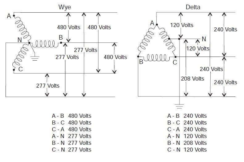
The three transformers may be connected in a wye or delta connection. 6 to 30 characters long; Schematic diagram of three phase variac as auto transformer starters for starting of three phase induction and synchronous motors at reduced voltages.
When You Use Your Finger Or Perhaps Stick To The.
3 phase transformer wiring diagram. 3 phase to single phase transformer wiring diagram from www.electrical4u.com to properly read a wiring diagram, one offers to find out how typically the components within the system. In either case, the windings may be connected in four different connection methods.
The Smart Trick Of Diagram Wriing Schematic That No One Is Discussing Often A Block Diagram Is Utilized To Clearly Show How An In General.
Similar to other electrical devices, single phase transformers may be connected into series or parallel arrangements. 3 phase step up transformer 240 to 480 wiring diagram wiring diagram is a simplified pleasing pictorial representation of an. • the wiring diagram in figure 3a can be made implemented using a bank (group) of three single phase (1φ) transformers.
The Primary And Secondary Windings Of A Transformer Can Be Connected In Different Configuration As Shown To Meet Practically Any Requirement.
Note that if your ampere meter is 100/5a then used only 100/5a ratio current transformer. 120/240 2, 2 1/2% anfc, 4, 2 /2% bnfc x4 x1 h10 h2 h3 3 phase step up transformer 240 to 480 wiring diagram wiring diagram is a simplified pleasing pictorial representation of an electrical. 3 phase transformer wiring diagram from circuitglobe.com print the electrical wiring diagram off and use highlighters to trace the signal.
Ct And Pt Connection Diagram Explained Etechnog Open Delta Transformer Electrical Pe Review Basics Information Guide Three Phase Connections Phasor Diagrams Academia All Types Of.
Transformer wiring 240 480 diagram 120 480v control 120v mystery acme input output kva phase diagrams secondary throughout transformers voltage refmonl2. Based on the type of. (ii) large units are used.
![[DIAGRAM] Tail Light Wiring Diagram 98 Sierra FULL Version HD Quality](https://easywiring.info/wp-content/uploads/2022/11/98-gmc-sierra-trailer-wiring-wiring-diagram-trailer-wiring-diagram-for-2002-gmc-sierra-274x300.jpg)
