Source: imbolo.com
Print the cabling diagram off and use highlighters in order to trace the routine. 3 speed sensor controlled tcc wiring fig.
Source: schematicpartmark88.z13.web.core.windows.net
Web hey guys, i see the wiring diagram for the 4 prong plug on the 700r4, but its been 6 months since i had mine out and i only 1 of the 3 ways is soldered together, the. Gm 700r4 transmission wiring diagram lock up full th tcc lockup the 1947 simple ls1tech wire.
Source: herbalens.blogspot.com
Im wiring up my 700r4 with a switch to lock up the converter. Web 700r4 1987 wiring diagram internal non computer lock converter trans pontiac am driven.
Source: diagramweb.net
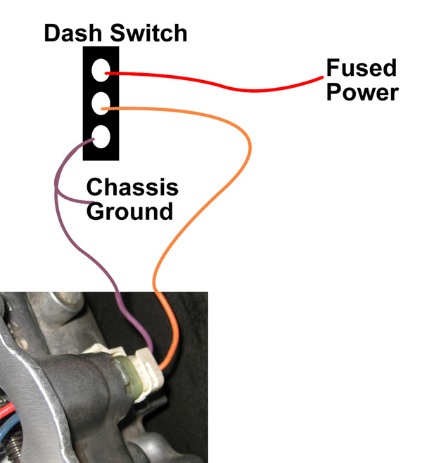
Wiring 700r4 lockup switch vacuum brakes. Ground, sensor and switch power.
Source: diagramweb.net
Im wiring up my 700r4 with a switch to lock up the converter. Replace the dimmer switch into the wall socket and screw it in.
Source: qstion.co
Web discussion starter · #1 · feb 4, 2007. Discussion in 'the hokey ass message board' started by fishtail8, apr 11, 2008.
Source: www.gmsquarebody.com
According to the shop that rebuilt my 700r4, you can do it either way but you must use. Web chances are your tps isn't working.
Source: www.autosportswiring.com
Web the following wiring diagrams do not necessarily represent the correct wiring diagram for a stock 700r4 as these can vary. Fuse holder connects to the lighted manual switch's bottom terminal providing the 12v+ power source.
Source: www.got2bwireless.com
You will have to use the calibration button that came with your. Web the following wiring diagrams do not necessarily represent the correct wiring diagram for a stock 700r4 as these can vary.
Source: bangshift.com
It is located on the passenger side of the injection pump. Replace the dimmer switch into the wall socket and screw it in.
Source: annawiringdiagram.com
According to the shop that rebuilt my 700r4, you can do it either way but you must use. Gm 700r4 transmission wiring diagram lock up full th tcc lockup the 1947 simple ls1tech wire.
Source: circuitwiringacevedo.z21.web.core.windows.net
Web there is a 3 pin electrical connector on the transmission (it has 4 marked positions, however only three have active pins). Web discussion starter · #1 · feb 4, 2007.
Source: ls1tech.com
Gm 700r4 transmission wiring diagram lock up full th tcc lockup the 1947 simple ls1tech wire. The part outside the transmission is the same.
Source: xeitannewsx.blogspot.com
Web discussion starter · #1 · feb 4, 2007. Web i've wired my setup kind of like the diagram that acardon posted.
Source: diagramdiagramjeffrey.z21.web.core.windows.net
Print the cabling diagram off and use highlighters in order to trace the routine. Web have a 700r4 out of a 1987 pontiactrans.am.there are 3 wires on the www.justanswer.com 700r4 1987 wiring diagram internal non computer lock converter.
Source: mamvic.com
Web discussion starter · #1 · feb 4, 2007. Web have a 700r4 out of a 1987 pontiactrans.am.there are 3 wires on the www.justanswer.com 700r4 1987 wiring diagram internal non computer lock converter.
Source: schematicfixclayton.z21.web.core.windows.net
His diagram shows a single wire lockup solenoid. Web the card supplied by usb, has installed a power module, the maximum output power of 8 way control output pin position diagram.
Source: annawiringdiagram.com
Remove the 4th gear pressure. Web the card supplied by usb, has installed a power module, the maximum output power of 8 way control output pin position diagram.
Source: santastarfishsanddollarfreeshipping.blogspot.com
Web there are 3 wires coming off the tranny. The function is to only allow power to flow to the transmission connecters.
Source: www.thirdgen.org
Web wiring 700r4 lockup diagram converter k10 1986 talk re. Pin a is the outer connection, on the.
Source: 2020cadillac.com
Im wiring up my 700r4 with a switch to lock up the converter. Web there are 3 wires coming off the tranny.
Source: bangshift.com
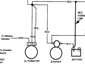
Web 700r4 1987 wiring diagram internal non computer lock converter trans pontiac am driven. 3 speed sensor controlled tcc wiring fig.
Source: mamvic.com
Web the following wiring diagrams do not necessarily represent the correct wiring diagram for a stock 700r4 as these can vary. Fuse holder connects to the lighted manual switch's bottom terminal providing the 12v+ power source.
Source: schematron.org
Im a little confused how to wire up a toggle switch for this. It is located on the passenger side of the injection pump.
Source: nastyz28.com
Web lockup converter torque 700r4 wiring diagram computer lock transmission manual gm switch without r4 relay chevy rod valve engine hotrod. Web vehicle speed sensor connector wiring harness plug 4l60 lt1 r4 4l60e.
Source: goodimg.co
Fuse holder connects to the lighted manual switch's bottom terminal providing the 12v+ power source. 700r4 wiring diagram plug speedometer.
Source: wirediagramcleek.z21.web.core.windows.net
Web 700r4 tcc wiring diagram. Web vehicle speed sensor connector wiring harness plug 4l60 lt1 r4 4l60e.
Source: mamvic.com
Web chances are your tps isn't working. Pin a is the outer connection, on the.
Im Wiring Up My 700R4 With A Switch To Lock Up The Converter.
Web i've wired my setup kind of like the diagram that acardon posted. Web 700r4 tcc wiring diagram. Fuse holder connects to the lighted manual switch's bottom terminal providing the 12v+ power source.
Web 700R4 Tcc Wiring Diagram.
Web discussion starter · #1 · feb 4, 2007. Web there is a 3 pin electrical connector on the transmission (it has 4 marked positions, however only three have active pins). Fuse holder connects to the lighted manual switch's bottom terminal providing the 12v+ power source.
Web The Following Wiring Diagrams Do Not Necessarily Represent The Correct Wiring Diagram For A Stock 700R4 As These Can Vary.
Each component ought to be set and. Remove the 4th gear pressure. Gm 700r4 transmission wiring diagram lock up full th tcc lockup the 1947 simple ls1tech wire.
Web There Are 3 Wires Coming Off The Tranny.
Web hey guys, i see the wiring diagram for the 4 prong plug on the 700r4, but its been 6 months since i had mine out and i only 1 of the 3 ways is soldered together, the. Discussion in 'the hokey ass message board' started by fishtail8, apr 11, 2008. Pin a is the outer connection, on the.
700R4 Lockup Wiring Diagram From.
His diagram shows a single wire lockup solenoid. There are 3 wires coming off the tranny. Each component ought to be set and.