If the technician does not find power going to the sensor and if a broken wire cannot be found easily it is best to go straight to the pcm and find the wire related to the oxygen sensor heater. Oxygen sensor harness wiring chevy tahoe forum gmc yukon 1992 silverado diagram base website 23o23e 3 way switch 2002 s10 4 can i have the for o2 snake marllboro6 abinbev regional de chrysler concorde intrepid lhs new yorker vision 1993 1997 bank 1 camaro5 page hhr ant oxygen sensor harness wiring chevy tahoe forum gmc yukon 1992 silverado read more.
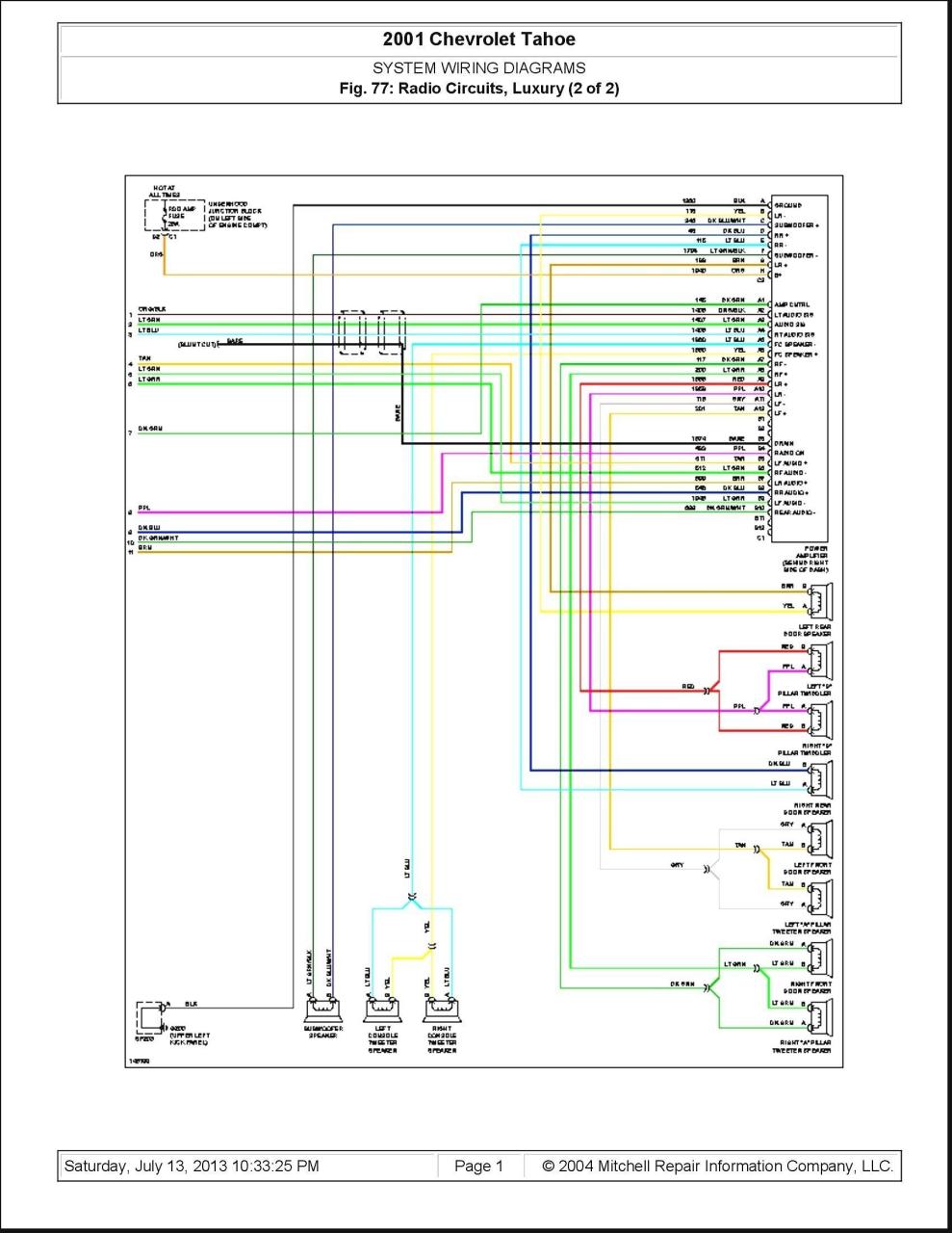
New Delco Amplifier Wiring Diagram Diagram Diagramtemplate Diagramsample Diagram Chevy Impala Radio
Testing the oxygen sensor commonly referred to as o2 sensors on your 4 3l 5 0l or 5 7l gm vehicle is not that hard to do.

Chevy 4 wire o2 sensor wiring diagram. You want to look at your sensor end and match it to our chart. On types 2 4 pay attention to the plastic guide s inside the tube between the pins. Type 2 has a guide on one side type 4 has guides on each side between the pins.
2008 system wiring diagrams chevrolet silverado 1500 2008 chevrolet silverado owner manual download pdf 2008 silverado 2008 b owner manual download pdf. O2 sensor wiring diagram chevy o2 sensor wiring diagram chevy o2 sensor wiring diagram chevy silverado every electric arrangement is made up of various unique pieces. In the case i was called in on the vehicle was a 2000 jeep grand cherokee with the 4 0l engine.
Since oxygen sensors are not cheap and sometimes the pcm powertrain control module fuel injection computer accuses them of being bad when they aren t testing them is a good idea and this article will help you. Each part ought to be set and connected with other parts in specific manner. Fortunately the sensor s negative heater wire was the only wire in the harness that was involved.
The vehicle s o 2 sensor harness was pinched underneath the valve cover at the back of the cylinder head. Factory sensor end type 1 this shows a factory o2 sensor end that has a type 1 connector. Back probing a pcm see figure 8 is as easy as finding the right colored wire from the wiring diagram and sticking a t pin into where the wire.
Otherwise the structure will not function as it ought to be.

16 Car Center Lock Wiring Diagram Car Diagram Wiringg Net Di 2020

Bmw E39 Electrical Wiring Diagram 4 Electrical Wiring Diagram Electricity Electrical Wiring

Yamaha Warrior 350 Wiring Diagram Images Pressauto Net Inside Electrical Diagram Diagram Buick Century

Pin On O2sensor

Wiring Diagram Ls1tech Wire Diagram Sensor

Gm Throttle Position Sensor Wiring Library Of Wiring Diagram Inside Throttle Position Sensor Wiring Diagram Diagram Mack Trucks Sensor

Pin On O2sensor

60 Beautiful 1979 Suzuki Gs1000 Wiring Diagram Images Yamaha V Star Suzuki Electrical Wiring Diagram

Pin On O2sensor

86 165v8tpi 4 For Tpi Wiring Harness Diagram In 2020 Diagram Design Diagram Sensor

Universal Lambda Sensor Oxygen Sensor 4 Wire High Quality Automotive Repair Oxygen Cars And Motorcycles

Engine Diagram For 7 Toyota Corolla Di 2020

4l60e Transmission Fuse Location Unique Wiring At 4l60e Diagram Best Of Chevy Transmission Electrical Diagram Transmission

Pin On Repair Info

Pin On O2sensor
Pin On O2sensor

2005 Chevrolet Cobalt Oxygen Sensor The Wires Are Different Colors With Images Chevrolet Cobalt 2005 Chevrolet Cobalt Oxygen

Jvc Kd R330 Wiring Diagram Best Of In 2020 Trailer Wiring Diagram Electrical Wiring Diagram Diagram

Dbw To Dbc Conversion 03 Harnesses Wiring Diagram Collection Inside Throttle Position Sensor Wiring Diagram Sensor Diagram Throttle