All of these wires are connected to the ecu. 2 & 3 wire crank sensor wiring diagram (with pictures) the crankshaft position. All of these wires are connected to the ecu.
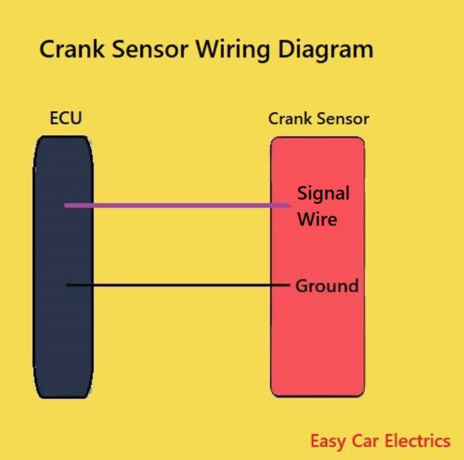
The 3 Wire Crank Sensor Has Three Wires Mentioned Below.
A 3 wire crank sensor receives a hot. The 3 wire crank sensor has three wires mentioned below. 2 & 3 wire crank sensor wiring diagram (with pictures) the crankshaft position.
Here Is A Wiring Diagram Of An Npn Sensor.
All three wires connect to the ecu. All of these wires are connected to the ecu. 3 wire crank sensor wiring diagram.
The 3 Wire Crank Sensor Has Three Wires Mentioned Below.
3 wire crank sensor wiring diagram. The 3 wire crank sensor has three wires mentioned below. The 3 wire speed sensor is externally powered, so you will.
Nissan Almera Tino V10 2001 Year Manual Part 46 Wiring Diagrams 199R10555 Wilbo666 Toyota.
All of these wires are connected to the ecu. All of these wires are connected to the ecu. 4.3 crank sensor wiring diagram.
3 Wire Crank Sensor Wiring Diagram.
The 3 wire crank sensor has three wires mentioned below. The gen iii crankshaft reluctor wheel is mounted on the rear of the crankshaft and within the engine block. All of these wires are connected to the ecu.