The tp sensor is a three wire potentiometer that provides an analog signal to the computer. But it doesn t mean link between the cables.
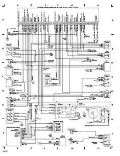
1986 Chevrolet C10 5 7 V8 Engine Wiring Diagram 1988 Chevrolet Fuse Block Wiring Diagram 20 Van V 8 In 2020 Electrical Wiring Diagram Chevy Trucks Chevy Pickups
Injunction of 2 wires is usually indicated by black dot in the junction of 2 lines.

Throttle position sensor wiring diagram. The megasquirt controller uses the throttle position sensor tps to determine when the engine is at or near full throttle to shut off feedback from the o2 sensor when the engine throttle is opening or closing rapidly and needing an accel decel enrichment and when the engine is flooded and needs to be cleared. Carries the throttle angle voltage signal that the tps creates to the pcm. Here s a brief description of the throttle position sensor tps circuits.
Vehicles included but not limited to would be. Occasionally the wires will cross. The pcm provides a sensor ground on the grn blk wire to a total of 6 components including your civic s throttle position sensor.
The car seems to still show some of the symptoms of the bad wiring fluctuating idle some smoke sometimes so now i need to check if my throttle actuator is in good condition so i am looking for the pin designation on the throttle actuator s plug or the internal diagram or schematic to make electrical tests to see if the throttle position. Also i show you how you can figure out what each wire on your sensor i. Throttle position sensor wiring diagram dodge throttle position sensor wiring diagram ford throttle position sensor wiring diagram gm throttle position sensor wiring diagram every electric structure is composed of.
Throttle position sensor tps wiring diagram part 2 throttle position sensor tps diagnostic troubleshooting notes. If you re testing for a short to ground a short to power or an open in this circuit then you ll need to unplug all of the sensors components this sensor ground wire connects to. Accelerator position sensor idlevalidation switch aps ivs diagnostics navpakž cec equipped engine control systems applies to.
2000 3400 3800 4000fbc 4000 8000 4300 4400 7400 7500 8500 ce bus re bus fe bus. The throttle position sensor tps wiring diagram and info in this page apply to 1997 1999 ford 4 6l 5 4l vehicles model years. The throttle position tp sensor and accelerator pedal position app sensor are the only sensors sending data to the powertrain control module pcm that the vehicle operator has direct control over.
All navpakž cec equipped engines 1998 through 2003 including t444e dt466e and 530e engines. As stated previous the lines at a throttle position sensor wiring diagramrepresents wires. Wire that feeds the tps with 5 volts dc from pin 90 of the pcm.
Here is a quick video on how to test a throttle position sensor tps with a multimeter.

Dbw To Dbc Conversion 03 Harnesses Wiring Diagram Collection Inside Throttle Position Sensor Wiring Diagram Sensor Diagram Throttle

06 Sorento Tps Wiring Diagram Trusted Wiring Diagrams Pertaining To Throttle Position Sensor Wiring Diagram Kia Sorento Kia Kia Picanto

2003 Dodge Ram 2500 Ecm Wiring Diagram Wiring Diagram By Car Electrical Wiring Wiring Diagram 2004 Dodge Ram 1500 Diagram Mack Trucks Sensor

See The Chevy Three Wire Throttle Position Sensor Wiring Diagram Chevytrucks Sensor Custom Chevy Trucks Throttle

Pin On Cars

Pin On Ratchets And Wrenches

Suzuki X3 Wiring Diagram In 2020 Ford Explorer Ford Ranger Diagram

Throttle Position Sensor Tps Wiring Diagram 1997 1999 Ford 4 6l 5 4l Sensor Throttle Diagram

Bmw Tps Wiring Find Wiring Diagram With Throttle Position Sensor Wiring Diagram Diagram Wire Positivity

Likewise Bmw Throttle Position Sensor On Bmw Wiring Diagram Online For Throttle Position Sensor Wiring Diagram Altima Nissan Nissan Altima

Ls3 Throttle Body Diagram Diagram Body Diagram Yamaha Engines

Pin On Ratchets And Wrenches

Gm Throttle Position Sensor Wiring Library Of Wiring Diagram Inside Throttle Position Sensor Wiring Diagram Diagram Mack Trucks Sensor
Bmw E36 Fuse Box Diagram Bmw Throttle Position Sensor Mercedes Benz Pertaining To Throttle Position Sensor Wiring Diagram Diagram Throttle Positivity

Throttle Position Sensor Tps Wiring Diagram 1997 1999 Ford 4 6l 5 4l Crankshaft Position Sensor Sensor Positivity

1990 Engine Performance Wiring Diagram With Control Module And Pertaining To Throttle Position Sensor Wiring Diagram Teknologi

Gm Throttle Position Sensor Wiring Library Of Wiring Diagram Pertaining To Throttle Position Sensor Wiring Diagram Positivity Sensor Throttle

Pin On Auto Electrical

Unique Dimmer Switch Wiring Diagram Manual Diagram Diagramtemplate Diagramsample Ingenieria Electronica Ingenieria Honda Wave