The push in connectors on ballasts have a button or slot to release each wire. Assortment of fluorescent ballast wiring diagram.
Broan 655 Wiring Diagram U2013 Vivresaville Com
Series ballast wiring 1 to 3 lamps.

4 pin cfl wiring diagram. 11 12 2018 11 12 2018 6 comments on 4 pin cfl wiring diagram this device is designed for use with 13ww 4 pin compact fluorescent lamps refer to lllustration 2 for switched and unswitched fixture wiring diagrams. For 4 pin compact fluorescent lamps dial the four digit extension of the factor. Unable to use these bulbs due to lack of wiring diagram ballast must be the item includes 1 pc plc lamp gx24q 4 pin base led cfl light compact fluorescent replacement bulb universal gx24q.
1 lamp instant start ballast diagram. 800 322 2086 fax. In this video i show in depth and step by step how to convert a 4 prong cfl can light fixture.
Commercial line voltage mostly uses 277 volts to power the lighting circuits. Cfl ballasts for 4 pin compact fluorescent lamps author. Bonlux 12w led gx24q 4 pin base light bulb 26w cfl compact fluorescent.
The 26 watt ballast shown below can be used for 1 or 2 lamps. Convert fluorescent to led wiring diagram fluro light wiring diagram australia new wiring diagram led symbol rh rccarsusa wiring a fluorescent led single pin t12 led wiring. It reveals the components of the circuit as streamlined forms and the power and also signal links in between the gadgets.
O hare international center 10275 west higgins road rosemont illinois 60018 telephone. Replaced the bulb under warranty however it comes from china and took 3 weeks. A replacement ballast.
Cfl ballasts and sockets have push in wire connectors. Electronic fluorescent datasheet created date. Convert your 4 prong cfl to an led super easy step by step.
Most newer cfl ballasts operate on 120v to 277v. A wiring diagram is a streamlined standard pictorial representation of an electric circuit. Wiring diagram number watts lamp data size 1 160 10 0 96 cfq13w g24q 13w cfl quad tube lamp pl c13w 4p f13dbx 4p cf13dd e 120.
Cfl ballasts for 4 pin compact fluorescent lamps advance transformer co. 1 lamp rapid start ballast diagram. Changing the wiring on a fluorescent light fixture from series to parallel involves changing the ballast from a series to a compatible parallel ballast.
Wiring diagram number watts lamp data size 1 160 10 0 96.

4 To 20 Ma Circuit Protection Circuit Diagram Di 2020

This Simple 20 Watt Home Emergency Tube Light Circuit Uses Very Few Components Yet Is Able To Produce Emergency Lighting Electronic Schematics Circuit Diagram

Pin On Circuit Design

Wiring Diagram Of Single Tube Light Installation With Electromagnetic Ballast Tube Light Light Switch Wiring Lighting Diagram

Cat 5a Wiring Diagram Ethernet Wiring Rj45 Electrical Circuit Diagram

Trailer Wiring Diagram Light Plug Brakes Hitch 4 Pin Way Wire Trailer Wiring Diagram Trailer Light Wiring Utility Trailer

6v Emergency Light Circuit Led Emergency Lights Emergency Lighting Circuit Diagram

Converting A Dead Cfl Into An Led Tubelight Electronic Circuit Projects Circuit Projects Electronics Circuit

9 Watt Cfl Bulb Ballast Circuit Diagram In 2020 Cfl Bulbs Cfl Circuit

Trailer Wiring Diagrams For Single Axle Trailers And Tandem Axle Trailers Trailer Wiring Diagram Utility Trailer Trailer

Working Principle Of Cfl Bulb In 2020 Cfl Bulbs Cfl Bulb

Electrical Wiring Drawing Electrical Wiring Diy Electrical House Wiring

Rj45 Wiring Diagram Ethernet Cable Ethernet Wiring Network Cable

Pin On Compact Fluorescent

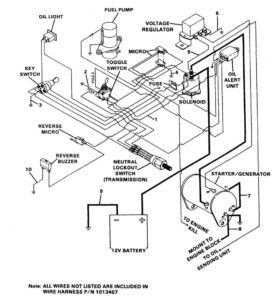
Wiring Diagram For Electric Scooters Electric Scooter Electrical Diagram Electricity
Ats Panel Genset Controller In Relay Panel Wiring Diagram Teknik Listrik Listrik Teknik

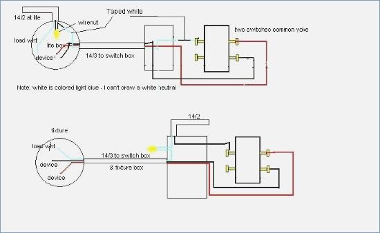
New Wiring Diagram For Multiple Lights On A Three Way Switch Diagrams Digramssample Diagramimages Ceiling Fan Wiring

Outstanding Fluorescent Light Ballast Circuit 33 Fluorescent Light Ballast Schematic Fluorescent Lamp Drive Fluorescent Light Fluorescent Lamp Circuit Diagram

A Complete Diagram Of Single Phase Distribution Board With Double Pole Mcb Wiring Rcd Wiring Distribution Board Electrical Circuit Diagram Electrical Projects