Table of wiring code in different countries. Black speed switch with only three terminals connected two wire capacitor.
Learn How To Do Ceiling Fan Capacitor Wiring With Diagram Ceiling Fan Wiring Ceiling Fan Ceiling Fan Motor
Speed switch connection table.

4 wire ceiling fan capacitor wiring diagram. Produced from superior quality aluminum alloy on high pr. Black speed switch three wire capacitor. Collection of 4 wire ceiling fan switch wiring diagram.
A wiring diagram is a streamlined standard pictorial depiction of an electrical circuit. It reveals the elements of the circuit as simplified shapes and the power and signal connections between the tools. 1 to l and c1 2 3 slow.
Wadoy cbb61 ceiling fan capacitor 4 wire for new tech vac 50 60hz 5uf 5uf zing ear zes6 3 speed 4 wire ceiling fan switch use for ceiling fans. Based on countries and their wiring code there are two major classifications. Cbb61 fan capacitor wiring diagram wiring diagram is a simplified conventional pictorial representation of an electrical circuit it shows the components of the circuit as simplified shapes and the capacity and signal connections in the company of the devices.
We bought a dual capacitor 3 speed fan switch replaced it wire for wire as it was before. 800 x 600 px source. 1 to l and c1 1 2 med.
This topic is a lot of individuals looking on the internet as. Fan with 3 wires as seen from fan side with capacitor 4 wire fan with inbuilt led light. Ceiling fan wiring diagram 2.
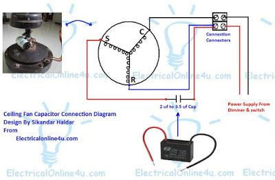
On this type of capacitor we have five wire in which two is common and 3 other for different value capacitance micro farad. 5 wire ceiling fan capacitor wiring diagram in ceiling fan we use the 5 wire capacitor for speeds low med and high speed. Switch that was supposed to replace a broken switch in a hunter ceiling fan once you identify the speed tap wire that makes the fan run the fastest connect that wire to 1 on the new switch.
3 speed 4 wire ceiling fan switch wiring our 3 speed fan pull chain broke with the short end of the chain in the housing of the switch. In the above ceiling fan capacitor wiring diagram i shown a symbol diagram of fan motor winding in which i shown start run and common wires i connect the common wire connection with one connection connector and then i connect the run wire to the other wire connector as i shown in above diagram with blue color line. 4 wire ceiling fan capacitor wiring diagram new unique wiring size.
Whatever you are we aim to bring the content that matches just what you are looking for. Considering all the above facts we have created a ceiling fan wiring diagram guide for ease of installation process. 1 to l c1 1 and c1 2.
Now in this you will learn about ceiling fan 5 wire capacitor and it s diagram. Ceiling fan wiring diagram 1. You may originate from an internet search engine after that discover this site.

How To Replace A Ceiling Fan Motor Capacitor Ceiling Fan Motor Ceiling Fan Pull Chain Ceiling Fan Switch

Hunter Ceiling Fan Speed Switch Wiring Diagram Ceiling Fan Wiring Hunter Ceiling Fans Ceiling Fan Switch

Wiring Diagram For Belle Minimix 150 Diagram Diagramtemplate Diagramsample

Ac Condenser Fan Motor Wiring Diagram 4 Wire Beautiful For New 7 Fan Motor Ceiling Fan Wiring Electrical Circuit Diagram

4 Wire Ceiling Fan Capacitor Wiring Diagram New Unique Wiring By Wiringforums In 2020 Ceiling Fan Switch Hunter Ceiling Fans Ceiling Fan Wiring

How To Connect Fan Regulator With Two Way Switch Cbb61 Capacitor 3 Ceiling Fan Wiring Ceiling Fan Fan Repair

Ceiling Fan Capacitor Wiring Diagram In Bangla Maintenance Work In Ceiling Fan Wiring Ceiling Fan Hunter Ceiling Fans

How To Replace A Capacitor In A Ceiling Fan 3 Ways In 2020 Ceiling Fan Capacitors Ceiling Fan Motor

Ceiling Fan Connection Of Four Wire Youtube Ceiling Fan Celing Fan Fan

Wiring Diagram Bathroom Lovely Wiring Diagram Bathroom Bathroom Fan Light Wiring Diagram Mikulskilaw Hunter Ceiling Fans Ceiling Fan Pulls Ceiling Fan Wiring

4 Wire Ceiling Fan Capacitor Wiring Diagram New Unique Wiring Ceiling Fan Switch Hunter Ceiling Fans Ceiling Fan Wiring

Ceiling Fan 3 Wire Capacitor Wiring Diagram Ceiling Fan Wiring Ceiling Fan Installation Fan Installation

Replacing Capacitor In Ceiling Fan With Diagrams Ceiling Fan Ceiling Fan Switch Ceiling Fan Wiring

Star Delta Wiring Diagram With Timer Pdf
Wiring Diagram For Capacitor With Images Ceiling Fan Switch Fan Motor Ceiling Fan Wiring

Wiring Diagram Car Radio

15 Electric Desk Fan Wiring Diagram Ceiling Fan Switch Stand Fan Desk Fan

New Industrial Exhaust Fan Wiring Diagram Diagram Diagramsample Diagramtemplate Wiringdiagram Ceiling Fan Switch Ceiling Fan Wiring Ceiling Fan Pull Chain

New Auto Gate Motor Wiring Diagram Pdf Ceiling Fan Switch Ceiling Fan Wiring Ceiling Fan Parts