4 wire ceiling fan switch wiring diagram what is a wiring diagram. A wiring diagram is a streamlined standard pictorial depiction of an electrical circuit.
4 Wire Ceiling Fan Wiring Diagram Ceiling Fan Wiring Ceiling Fan Pulls Ceiling Fan Pull Chain
The diagram above looks complicated but it s really not.

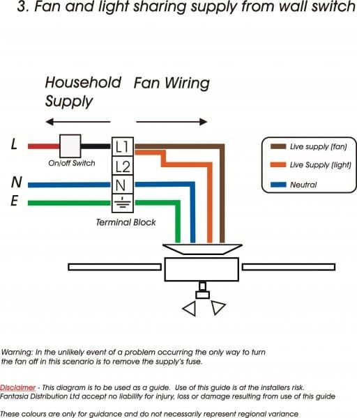
4 wire ceiling fan wiring diagram. Then leaving the double switch box is a 3 wire cable going to the ceiling fan and a 4 wire cable going to the other 3 way switch. 4 wire ceiling fan switch wiring diagram source. Pick the diagram that is most like the scenario you are in and see if you can wire up your fan.
With these diagrams below it will take the guess work out. A wiring diagram is an easy visual representation with the physical connections and physical layout associated with an electrical system or circuit. Whether you are looking to wire a ceiling fan with lights to one power switch or add a fan in a room without a switch source this guide will teach you how to wire a ceiling fan using four common scenarios and the best wiring methods.
Notice this circuit has a 3 wire cable power source coming into the double switch box. Collection of 4 wire ceiling fan switch wiring diagram. Read nest compatbilty wiring diagram database.
Just focus on one circuit one at a time and it will fall right into place. 2005 gmc sierra 2500 trailer fuse wiring pictures. This might seem intimidating but it does not have to be.
It shows the way the electrical wires are interconnected which enable it to also show where fixtures and components could. Take a closer look at a ceiling fan wiring diagram. It reveals the elements of the circuit as simplified shapes and the power and signal connections between the tools.
4 wire ceiling fan switch wiring diagram source. Wiring ceiling fans can seem complicated but the task really just depends on the type of fan you are installing and how you want it to operate.

Credit Image Http Wirings Diagram Com Ceiling Fans Info Source Ceiling Fan Wiring Ceiling Fan Int In 2020 Ceiling Fan Wiring Ceiling Fan With Light Ceiling Fan

Wiring Diagram For Ceiling Fan With Light Australia Bookingritzcarlton Info Ceiling Fan Wiring Ceiling Fan Switch Ceiling Fan Installation

Ac Condenser Fan Motor Wiring Diagram 4 Wire Beautiful For New 7 Fan Motor Ceiling Fan Wiring Electrical Circuit Diagram

Wiring Diagram For Ceiling Fan Switch Bookingritzcarlton Info Ceiling Fan Switch Ceiling Fan Light Pulls Ceiling Fan Wiring

Need Help Replacing Hvac Condensor Fan Motor 3 Wire Old To 4 Wire New Ceiling Fan Wiring Ceiling Fan Switch Fan Motor

Ceiling Fan Wiring Diagram 1 Ceiling Fan Wiring Home Electrical Wiring Ceiling Fan Installation

Wiring Speed Cables On Off Speeds Ceiling Fan Ceiling Fan Pull Chain Ceiling Fan Pulls Ceiling Fan With Light

Hook Up Ceiling Fan 4 Wires 4 Wire Ceiling Fan Switch Ceiling Fan Switch Ceiling Fan Wiring Ceiling Fan With Light

Ceiling Fan Wiring Diagram 7 Yugteatr Ceiling Fan Wiring Home Electrical Wiring House Wiring
4 Wire Ceiling Fan Capacitor Wiring Diagram New Unique Wiring Ceiling Fan Switch Hunter Ceiling Fans Ceiling Fan Wiring

Ceiling Fan Wiring Diagram Ceiling Fan Wiring Diy Electrical Home Electrical Wiring

Pin On Wires

Wiring Diagram For 4 Lights With One Switch Inspirational Dual Light Inside Wiring 4 Lights To One Swit Light Switch Wiring Ceiling Fan Wiring Fan Light Switch

Best Of Ceiling Fan Light 3 Way Switch Wiring And View In 2020 Ceiling Fan Switch Ceiling Fan Wiring Ceiling Fan With Light

Ceiling Fan Connection Of Four Wire Youtube Ceiling Fan Celing Fan Fan

Ceiling Fan Speed Switch Wiring Diagram Ceiling Fan With Light Fan Light Switch Ceiling Fan Switch

14 Automatic Wiring Diagram For Ceiling Fan In 2020 Ceiling Fan Wiring Ceiling Fan Installation Ceiling Fan With Remote

Hunter Ceiling Fan Speed Switch Wiring Diagram Ceiling Fan Wiring Hunter Ceiling Fans Ceiling Fan Switch

How To Connect Fan Regulator With Two Way Switch Cbb61 Capacitor 3 Ceiling Fan Wiring Ceiling Fan Fan Repair