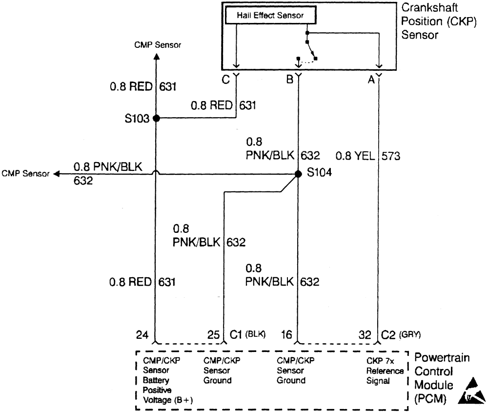
5.3 Crankshaft Position Sensor Wiring Diagram. Restore the pcm battery feed. This is the reason the inductive type crankshaft position sensor has two wires.
Repair Guides from www.autozone.com
Brown/white, yellow, black, and red. 2 wire crank sensor wiring diagram 2 wire crank sensor wiring diagram. At this time, plug the new crankshaft position sensor into the engine wiring harness.
I will attach the wiring diagram for you to view. 2 wire crank sensor wiring diagram 2 wire crank sensor wiring diagram. Restore the pcm battery feed.
This Is The Reason The Inductive Type Crankshaft Position Sensor Has Two Wires.
When the crankshafts reluctor ring comes closer to the crank. Just need an illustration of the wire color positions in the crankshaft position sensor pigtail for a 2003 chevy tahoe z71 5.3. This is the reason the inductive type crankshaft position sensor has two wires.
4.8, 5.3, 6.0 And 6.2 The Crankshaft Position.
This is the reason the inductive type crankshaft position sensor has two wires. At this time, plug the new crankshaft position sensor into the engine wiring harness. However the crank position sensor wiring isnt connected to anything.
5.3 Crankshaft Position Sensor Wiring Diagram.
This is the reason the inductive type crankshaft position sensor has two wires. The gmc yukon utilizes a crankshaft position sensor in order to regulate the. This is the reason the inductive type crankshaft position sensor has two wires.
A Wiring Diagram Makes It Easier To Check For Shorts To Ground Or Power And Of Course Check For Continuity Between The Crank Sensor And The Pcm.
This is the reason the inductive type crankshaft position sensor has two wires. Either install a brake switch or look at your wiring. The next step is to firmly twist the new crankshaft position sensor and reinstall the bolts.