A wiring diagram is a simplified traditional pictorial depiction of an electrical circuit. Voltage sensing relay wiring diagram.
Best Relay Wiring Diagram 5 Pin Wiring Electrical Circuit Diagram Circuit Diagram Electrical Diagram
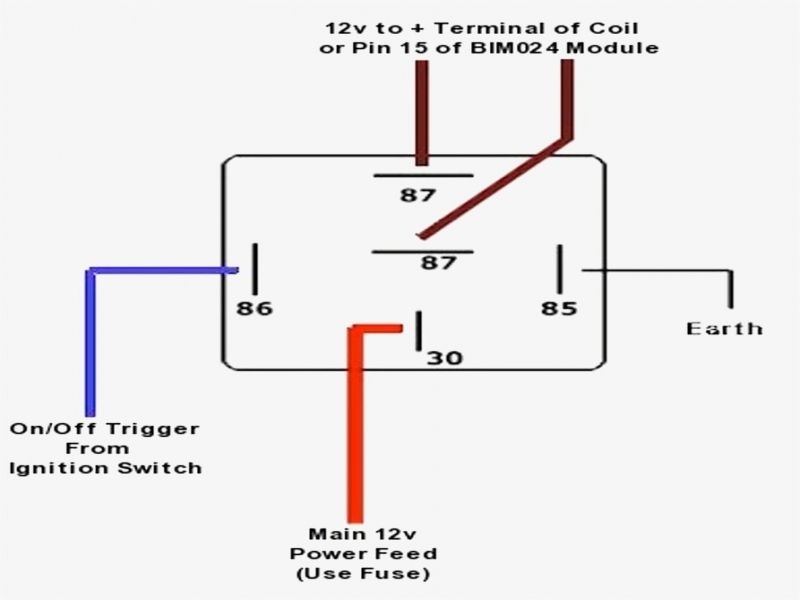
12 volt 4 pin relay wiring diagrams within 12v 5 pin relay wiring diagram image size 983 x 612 px image source.

12v timer relay wiring diagram. Caravan relay wiring diagram valid elegant 12 volt relay wiring. This pinout image is only a 2 pole diagram for room on the page purposes but you can get the picture here with this one since a 3 pole will just have 1 more set of contacts. Wiring the relay as shown will cause the voltage across pins 5 and 6 to change from 12v to 12v.
The square relay pinout shows how the relay socket is configured for wiring. 12 volt relay wiring diagram sample relay case how to use relays and why you need them allcylinders. Wiring the relay creates a half bridge.
Here is a picture gallery about 12v 5 pin relay wiring diagram complete with the description of the image please find the image you need. Voltage sensing relay wiring diagram. In addition wiring diagram provides you with time body by which the tasks are to be completed.
When 12v is applied to pin 8 the relay will activate. Multiple 12v relay wiring diagram wiring diagram 12 volt relay wiring diagram. The actuator can be wired in 2 ways.
Assortment of 12 volt relay wiring diagram. You will be able to know precisely if the projects needs to be finished which makes it much easier for you to effectively handle your time. 12v timer relay wiring diagram wiring diagram is a simplified pleasing pictorial representation of an electrical circuit it shows the components of the circuit as simplified shapes and the knack and signal friends amongst the devices.
It reveals the components of the circuit as simplified shapes and also the power and signal connections in between the tools. The default position of the relay is when the relay is deactivated the active position is when pin 8 has 12v on it. This video is about 12v dc timer model cn101a sold on ebay and amazon.

Wiring Diagram For 5 Pin Relay 5 Pin Relay Wiring Diagram Wiring Electricite Auto Auto Electronique
12v Universal Heated Rear Window Timer Relay 10 Min Delay Timer Relay Digital Timer

5 Pin Relay With Diode Wiring Diagram Electrical Circuit Diagram Electrical Wiring Diagram Diagram

Diagram By Akita Your Diagram Source From Akita Automotive Electrical Relay Automotive Mechanic

8 Pin Relay Ladder Diagram Electrical Circuit Diagram Circuit Diagram Trailer Wiring Diagram

12v Universal Intermittent Wiper Timer Relay 5 Sec Delay In 2020 Car Audio Installation Motorcycle Wiring Electrical Diagram

Interally Relay Wiring Diagram Automotive Mechanic Automotive Electrical Electronic Circuit Projects

12v Relay Wiring Diagram 5 Pin Circuit Diagram Relay Electrical Diagram

50 Fresh 12 Volt Relay Wiring Diagram In 2020 Circuit Diagram Relay Electrical Diagram

5 Pin 30 Amp Relay Wiring Diagram Best Of 12v Deltagenerali Me Electric Radiator Fan Radiator Fan Electric Radiators


Electric Fan Relay Wiring Diagram Electricity Electric Fan Automotive Mechanic

30 Automotive Relay Wiring Diagram Relay Electrical Diagram Diagram

Automotive Relay Guide 12 Volt Planet For Wiring Diagram Cruiserboataccessories Automotive Electrical Automotive Mechanic Electricity

Best 12v Relay Wiring Diagram Pin At Switch 5 How To Wire A Electrical Diagram Circuit Diagram Automotive Electrical

Simple 5 Pin Relay Diagram Dsmtuners Circuit Diagram Relay Diagram

12v Relay Circuit Tags Wiring Diagram Car Amp In 12 Volt Carlplant For Relays 1015×1024 In 12 Vo With Images Motorcycle Wiring Automotive Electrical Car Audio Installation

12v Relay Wiring Diagram 5 Pin Relay Fuse Box Diagram