On this page we will explain the principle according to which modern pedal travel transmitters operate and which symptoms indicate a fault in this. I need the wire diagram for the peterbilt side of the throttle position sensor.
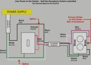
Unique Dimmer Switch Wiring Diagram Manual Diagram Diagramtemplate Diagramsample Ingenieria Electronica Ingenieria Honda Wave
I just got through resolving code p0134 o2 sensor sensor circuit no activity on a 2000 jetta vr6.

Accelerator pedal position sensor wiring diagram. Mounted on the accelerator pedal. In doing so they removed the pins from the 3 pin connector on the floor. Replacing the o2 sensor along with the ecu eliminated the code.
The gm camshaft position sensor replacement cost the average cost for a chevrolet corvette camshaft position sensor replacement is between and labor costs are estimated between 61 and while parts are priced between 65. The accelerator pedal sensor transmits the position of the accelerator pedal to the engine control unit. The unit had a brake in the original oem harness to the ecm.
The o2 wiring was frayed and fried the ecu circuitry which controls it. Wm476c d 68 pneumatic throttle pedal alternate substitution wm476f5a2 wm476f5a1 b 70 pneumatic throttle pedal wm117209 wm476f5a2 d 70 pneumatic throttle pedal wm130634 wm499c d 72 relay air start wm113470 wm511c c 74 hyd proportional pedal wm119130 wm512c c 76 hyd throttle cylinder wm119436 wm513a b 78 q r. Accelerator pedal position sensor wiring diagram wiring diagram is a simplified satisfactory pictorial representation of an electrical circuit it shows the components of the circuit as simplified shapes and the skill and signal links amongst the devices.
Accelerator position sensor aps the ecm sends a regulated 5v signal through the ecm black chassis connector terminal 3 to aps connector terminal c. Wire colors a red with org trace blue and black with white trace. Now i have code 00777 accelerator position sensor g79 27 10 implausible signal intermittent.
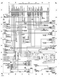
C6 corvette wiring diagram for cam position sensor. Pin 19 engine coolant temp sensor pin 20 engine start pin 21 air conditioner system switching pin 22 neutral position signal auto pin 23 accelerator pedal position sender pin 24 automatic transmission signal 1 pin 25 atcp module if fitted pin 26 vehicle speed signal pin 29 accelerator pedal switch pin 30 automatic transmission signal 3. A pete dealer by passed the harness and went straight to the ecm.
The c6 corvette accelerator pedal can be used with the harness. The accelerator pedal assembly is serviceable to the extent that the aps ivs switch can be replaced without replacing the complete assembly. 6 pedal sensor 2 tc pin 25 ecu pin ana1 input pedal sensor pedal sensor bosch 021 907 475d pedal sensor valeo 445 821 001 001 throttle body throttle body bosch 0280 750 085 throttle body bosch 0280 750 036 1 motor 2 tc pin 9 2 motor 1 tc pin 8 3 signal gnd 4 butterfly sensor 2 5 5v 6 butterfly sensor 1 ecu tps input.
Based on this information the load requested by the driver can be implemented immediately.

See The Chevy Three Wire Throttle Position Sensor Wiring Diagram Chevytrucks Sensor Custom Chevy Trucks Throttle

Throttle Position Sensor Tps Wiring Diagram 1997 1999 Ford 4 6l 5 4l Sensor Throttle Diagram

Unique 2007 Dodge Ram 1500 Headlight Wiring Diagram Diagram Diagramsample Diagramtemplate Wiringdiagram D 2004 Dodge Ram 1500 Dodge Ram 2500 Cummins Dodge

Kia Sorento 2006 Model D4cb Accelerator Pedal Position Sensor Electrical Diagram Google Search Acoustic Control Engine Control Unit System

Gm Throttle Position Sensor Wiring Library Of Wiring Diagram Pertaining To Throttle Position Sensor Wiring Diagram Positivity Sensor Throttle

Pin On Auto Electrical

2003 Dodge Ram 2500 Ecm Wiring Diagram Wiring Diagram By Car Electrical Wiring Wiring Diagram 2004 Dodge Ram 1500 Diagram Mack Trucks Sensor

Dbw To Dbc Conversion 03 Harnesses Wiring Diagram Collection Inside Throttle Position Sensor Wiring Diagram Sensor Diagram Throttle

Kia Sorento 2006 Model D4cb Accelerator Pedal Position Sensor Electrical Diagram Google Search Mitsubishi Outlander Outlander Diagram

Gm Throttle Position Sensor Wiring Library Of Wiring Diagram Inside Throttle Position Sensor Wiring Diagram Diagram Mack Trucks Sensor

Likewise Bmw Throttle Position Sensor On Bmw Wiring Diagram Online For Throttle Position Sensor Wiring Diagram Altima Nissan Nissan Altima

Ls3 Throttle Body Diagram Diagram Body Diagram Yamaha Engines

06 Sorento Tps Wiring Diagram Trusted Wiring Diagrams Pertaining To Throttle Position Sensor Wiring Diagram Kia Sorento Kia Kia Picanto

Pin On Toyota Corolla
Bmw E36 Fuse Box Diagram Bmw Throttle Position Sensor Mercedes Benz Pertaining To Throttle Position Sensor Wiring Diagram Diagram Throttle Positivity

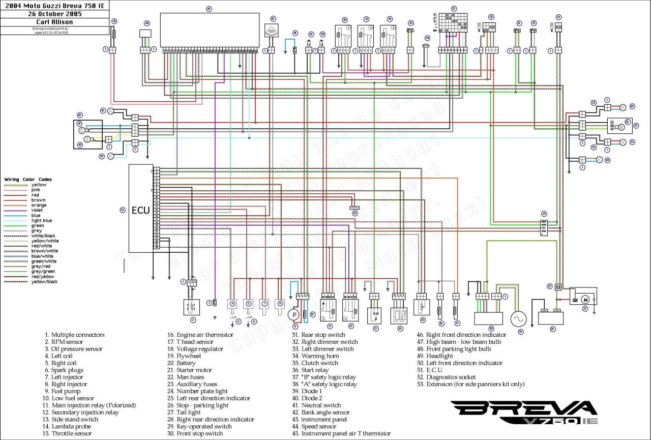
Exelent Free Vehicle Wiring Diagrams Download 2001 Honda Shadow Spirit 750 Wiring Diagram Wiring Di Electrical Wiring Diagram Diagram Design Electrical Diagram

Bmw Tps Wiring Find Wiring Diagram With Throttle Position Sensor Wiring Diagram Diagram Wire Positivity

Wiring Diagram For Electric Scooter Bookingritzcarlton Info Electrical Wiring Diagram 150cc Scooter Chinese Scooters

1990 Engine Performance Wiring Diagram With Control Module And Pertaining To Throttle Position Sensor Wiring Diagram Teknologi