Pinout diagrams and wire colours for cat 5e cat 6 and cat 7. The dmx specification allows for two completely separate data channels over the one 5 pin connector but often you ll find the cable manufacturers cheap out and only provide a single channel.
Pin On Inr Wiring Diagram
Here is a picture gallery about 5 pin din plug wiring diagram complete with the description of the image please find the image you need.

5 pin din wiring diagram. 3 phase 5 pin plug wiring diagram. Rj45 wiring pinout for crossover and straight through lan ethernet network cables. 5 pin xlr connectors are used primarily in lighting control applications as a dmx signal.
5 pin din plug wiring diagram dmx cable wiring diagram connector my wiring diagram 5 pin din plug wiring diagram wiring diagram is a simplified welcome pictorial representation of an electrical circuit. 5 pin xlr wiring standard. A four conductor cord wired in this way is sometimes called a din cord a din lead or a din cable.
5 pin din audio connections. The three pins that make contact with a 3 pin din connector will have the same pin numbering both in the three pin and the five pin connector. Pinout of din audio and layout of 5 pin din female connector and 5 pin din male connector.
Holes on female connectors are also numbered 1 4 2 5 3 but from left to right facing the holes. 5 pin din connector wiring diagram wiring schematic diagram 54. Din plug wiring diagram pin din to rca plug wiring diagram images for 5 pin din plug wiring diagram image size 429 x 392 px image source.
Take the insulation wires and strip about inch on the ends. Vs 36mt120 vishay vs 36mt120 3 phase bridge rectifier 35a 1200v. How to wiring the cable of 5p industrial sockets and plugs.
Here is the dmx pin out. Viewed from the solder side of the plug or from the face of the socket on the amplifier. Pin 1 left in pin 2 signal ground pin 3 left out pin 4 right in pin 5 right out.
It shows the components of the circuit as simplified shapes and the facility and signal links between the devices. There is no standard pinout for 5 pin din audio connections but there is a common configuration.

Honda Car Radio Stereo Audio Wiring Diagram Autoradio Connector Wire Installation Schematic Schema Esquema De Conexiones Stecker Konektor Connecteur Cabl Di 2020 Diagram

Usb Wiring Diagram Computers In 2020 Usb Keyboard Usb Cable

Bescor 7 Pin Din Connector Pinout Shop Layout Socket Set Electronics

Unique Simple Switch Wiring Diagram Wiringdiagram Diagramming Diagramm Visuals Visualisation Graph Light Switch Wiring Diagram Generator Transfer Switch

Pin On Electronic Electric
New Car Stereo Power Amplifier Wiring Diagram Diagram Diagramtemplate Diagramsample Jetta A4 Jetta 2002 Sistema Electrico

Image Result For 8 Pin Din Connector Pinout Electronics Digital Control System

10382042 290351411131929 6280744195492862235 O Jpg 1 275 1 650 Pixels Automotive Electrical Trucks Repair

Relay 5 Pin Wiring Diagram Knitknot Info Relay Electronics Projects Diagram

51b7viqb0ll In Car Capacitor Wiring Diagram Speaker Lloudspeaker Audio Www Foraudiogeeks Com Car Audio Capacitor Car Audio Car Stereo Systems

5 Pin Wiring Diagram 12v Relay Din Plug S E Economy Straight Diagram Plugs Wire

C B Wire Diagram With Images Diagram Image Free Images

Xlr To Trs Wiring Diagram Free

6 Pin Mini Din Connector Pinout In 2020 Connector Serial Port Mini

How To Wire Ammeter Elegant In 2020 Electrical Wiring Diagram Light Switch Wiring Diagram

3 5mm Mini Stereo Cables To Midi 5 Pin Din Midi Pa System Audio Current Source

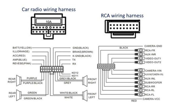
Pin On Car Mp5 Player

6 Pin Mini Din Connector Pinout In 2020 Mini Connector Pin

Trailer Wiring Connector Diagrams Conductor Plugs Wiring And Diagram In 2020 Trailer Wiring Diagram Trailer Light Wiring Electricity