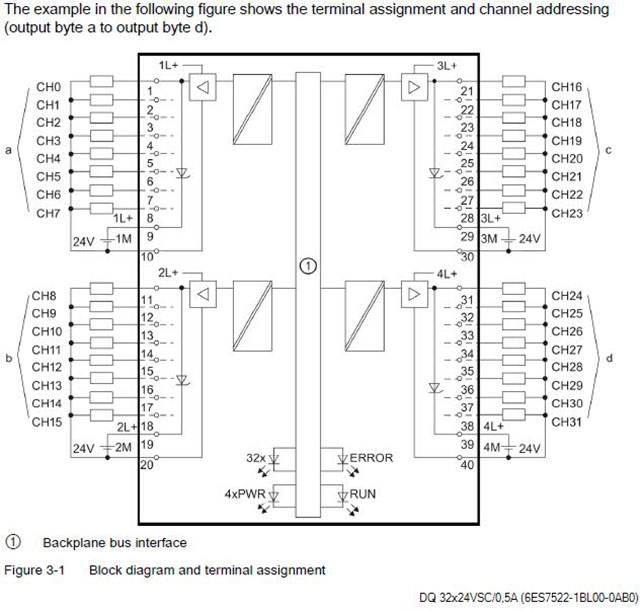
6Es7522-1Bl01-0Ab0 Wiring Diagram. Warranty terms and conditions if you need a specific. Yamazaki electric circuit wiring diagram.s module data manual, 08/, a5e 3 preface purpose of the manual the information contained in this manual can be used as a.
️6es7522 1bl01 0ab0 Wiring Diagram Free Download Gmbar.co from gmbar.co
0.25 mm2 to 1.5 mm2 (awg24 to 16) integrated potential bridges for flexible creation. 32 channels in groups of 8; Substitute value, switching cycle counter for connected.
If You Need A Specific.
32 channels in groups of 8; 32 channels in groups of 8; Check part details, parametric &.
The Step 7 Online Help Supports You In The Configuration And.
Warranty terms and conditions if you need a specific. 32 channels in groups of 8, 4 a per group; For logic links yes for uprating no for redundant control of a load yes switching frequency with resistive load, max.
0.25 Mm2 To 1.5 Mm2 (Awg24 To 16) Integrated Potential Bridges For Flexible Creation.
Substitute value, switching cycle counter for connected. Yamazaki electric circuit wiring diagram.s module data manual, 08/, a5e 3 preface purpose of the manual the information contained in this manual can be used as a. Encoders & measuring systems ,fans & batteries.
Substitute Value, Switching Cycle Counter For Connected.
Hope this helps, regards, fck. 100 hz with inductive load, max. Have a look into the manual, chapter 3, wiring:
Article Number (Market Facing Number) 6Es75111Ak020Ab0 | 6Es75111Ak020Ab0:
Продолжение предыдущих объяснений:варианты использования многорежимного модуля аналогового ввода 6es7331. 32 channels in groups of 8; Of which 2 inputs as counters can.