5 Pin Potentiometer Wiring Diagram. In the circuit diagram shown below, the terminals of the potentiometer are marked 1, 2 and 3. We have a resistive track whose.
عيد الشكر نسبيا مثير 5 pin potentiometer wiring from www.innerselfstudio.com
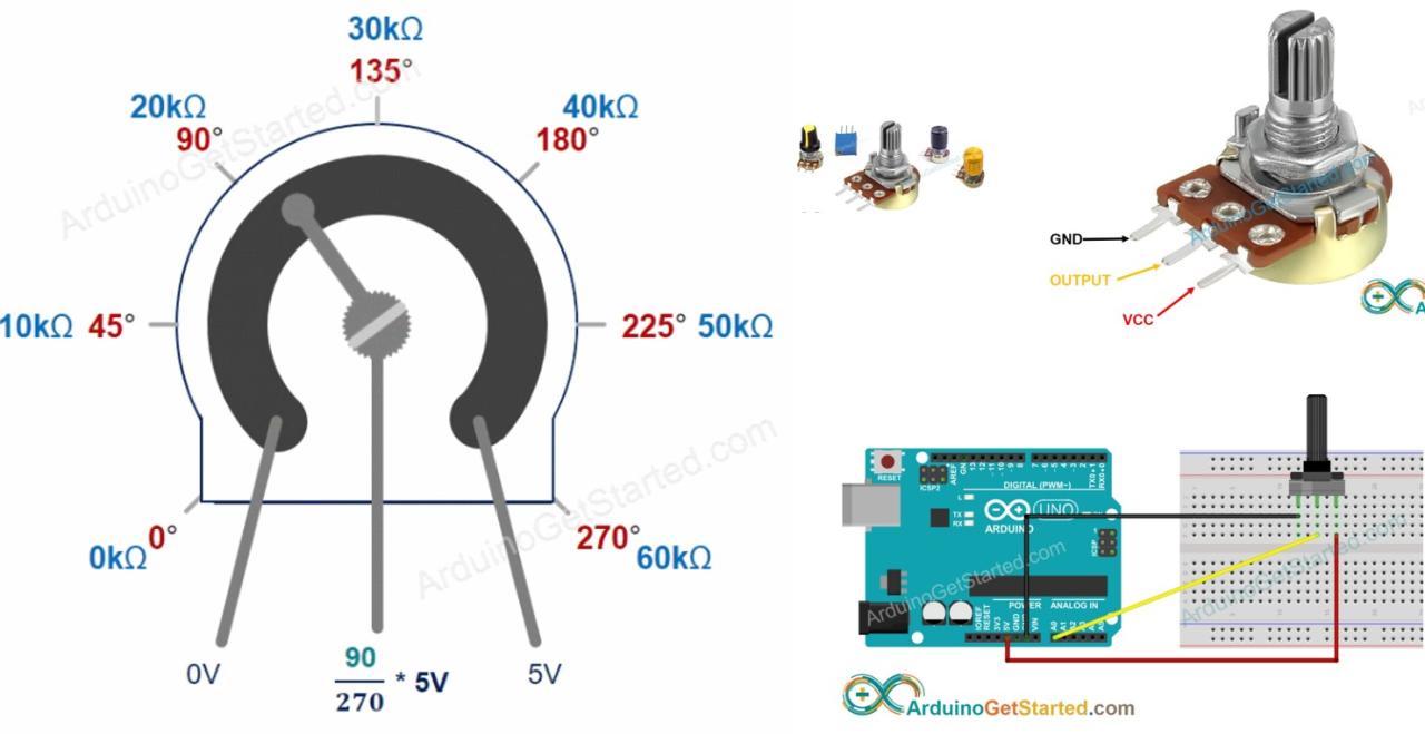
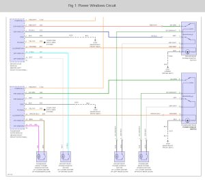
Tin a small length of wire by tapping the exposed part with your soldering iron and flux. Output of first variable resistance unit, channel 1. The voltage supply is connected across terminals 1 and 3, positive lead to terminal one while.
Then, Set Your Pot On A Flat Plane With.
October 21, 2015, 05:19:47 am ». Wiring up a potentiometer is so easy! The middle one connects somewhere between the ends.
Make Tight Wiring Connections Electricity Travels Along Conductors, Like Wires.
Now look at the other two pins. Once the wire soaks up some flux,. 5 pin thumbwheel variable resistor pinout.
The Best Way To Wire A Potentiometer As A Rheostat Is To Connect The Wiper And For Potentiometers Is 10 Kohm Other Very Common Values Are 1K, 5K And K.
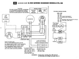
Motor positive motor negative signal wire (sensor 1) signal wire (sensor 2) hot power wire (5 volt reference. The potentiometer outputs are fed to the output power amplifier stage (s). Using a joystick on the raspberry pi using an mcp3008.
In The Circuit Diagram Shown Below, The Terminals Of The Potentiometer Are Marked 1, 2 And 3.
Next, you’ll need to supply an input signal to the. By connecting an output pin of the potentiometer. I know how to use it, but how many.
Seems Like It's More Difficult Than It Should Be Lol.
You should detect the 3 basic terminals sticking out of the center of the pot. Probably you'll find that the center pin has equal resistance to the 2 ends. Potentiometer as an electronic control unit.