Us Solid Motorized Ball Valve Wiring Diagram. Web motorized ball valve 9v, 12v to 24v, 5 wire setup with indicator wires. Web h wiring diagram of motorized valve covna actuator.
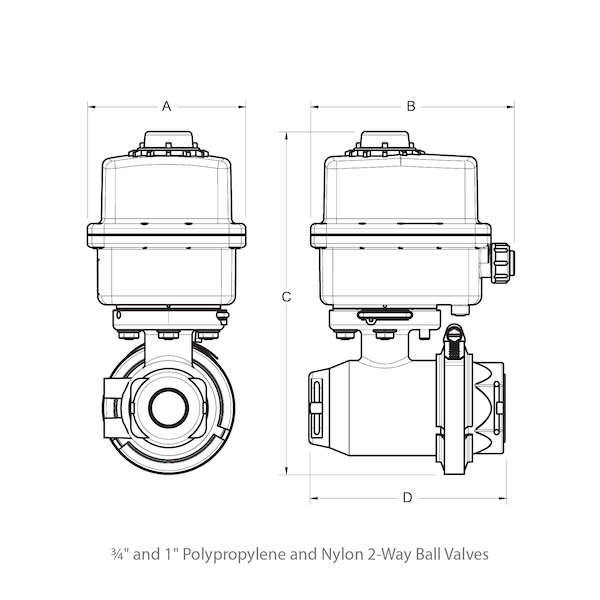
KZValve 2Way Motorized Ball Valves from kzvalve.com
Web h wiring diagram of motorized valve covna actuator. Automatic water shut off valve. Web us solid motorized ball valve wiring diagram.
Web Motorized Ball Valve 9V, 12V To 24V, 5 Wire Setup With Indicator Wires.
Power must in off position when start the manual override. This can be used with lights or a control system to monitor the status of the valve. Automatic water shut off valve.
When the valve is energized(by switching on), the valve will open.it will remain o. Motorized ball valves are a vital piece of equipment in. A wiring diagram will reveal you where the wires must be linked, so you do not have to think.
In case of an electric supply failure, it is possible to operate the actuator manually: Web this page consists of details on the u.s. The motorized valve comes with three wires primarily marked as blue, yellow and red.
While The Second Point Of Control Allows For Automation.
Web the yellow wire is the negative/ground/common from the valve. You don’t have to guess, a wiring. Web this page consists of details on the u.s.
Web The 2 Wire Auto Return Can Be Connected Directly To A Simple On/Offswitch.
We produced this page to assist those. The red wire will be positive to turn the valve one way, and blue will be positive to make it go the. Web in this 5 wire setup,the motorized ballvalve is hooked up to adpdt switch.