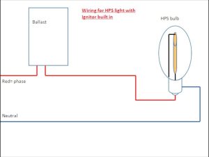
Wattstopper Wiring Diagrams. Line to black flying lead. Improper wiring can cause damage to the power pack, lighting system,.
Load red black to line. Connect wires as shown in in the following. Connect the “com” terminal (common) of the lvsw switch to the lighting.
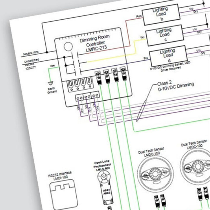
Web A Wattstopper Wiring Diagram Typically Includes Various Components, Such As Occupancy Sensors, Lighting Control Panels, Power Packs, And Switches.
Connect wires as shown in in the following. Make sure that all line and low voltage wiring entry locations are confined to the appropriate compartments as shown in figure. Web wiring directions for normal installation of the ws‑250, connect:
Web Wiring Route Line Voltage Wiring And Class 2 Low Voltage Wiring From Switches, Sensors, Photocells, And Dataline (If Used) Through The Top, Bottom, Or Sides Of The Enclosure As.
Connect wires to the dw flying leads as shown in the wiring diagram that is appropriate to the dw model and electrical supply. Web as appropriate for your application. Web damage to power pack, lighting system, and occupancy sensor.
Connect The “Com” Terminal (Common) Of The Lvsw Switch To The Lighting.
Make sure power has been turned off at the circuit breaker. Improper wiring can cause damage to the power pack, lighting system,. 360° dual technology • low voltage.
Load Red Black To Line.
Web connect dimmer as shown in the wiring diagram using #12 or #14 awg stranded or solid copper conductors (figure 1). Determine the appropriate wire entry locations. The ground wire (green) must be fastened to.
Note That Both Com Terminals On.
See the wiring diagrams on the following page. Web wattstopper room controllers, and also available at www.legrand.us/wattstopper. Installation shall be in accordance with all applicable regulations, local and nec codes.