Msd digital 6a and 6al ignition control 6a pn 6201 6al pn 6425. Otherwise the arrangement won t work as it ought to be.

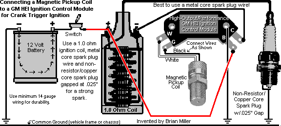
Gm 4 Pin Hei Electronic Ignition Control Module Wiring Connections Diagram With A Magnetic Pickup Coil Ignition Coil Coil Ignite
You can save this photograph file to your own pc.

Msd 6al wiring diagram chevy hei. If not the arrangement will not function as it ought to be. It reveals the parts of the circuit as simplified forms and also the power as well as signal links in between the tools. When this wire is used the magnetic pickup connector is not used.
This is the msd 6 wiring diagram msd 6al digital wiring wiring diagrams j of a pic i get off the chevrolet hei distributor wiring diagram package. Each component should be placed and linked to different parts in particular manner. Each part should be set and connected with different parts in specific manner.
For example in a chevy v8 the firing order is 1 8 4 3 6 5 7 2. A wiring diagram is a simplified traditional photographic depiction of an electric circuit. Amplifier output or to the yellow wire of an msd timing accessory.
Into the other wire. Please right click on the image and save the illustration. Our people also have some more pics connected to chevrolet hei distributor wiring diagram please see the pic gallery below click.
Msd 6al to hei wiring diagram wiring diagram hei wiring diagram msd 6al wiring diagram chevy. It reveals the elements of the circuit as simplified forms as well as the power as well as signal connections in between the devices. Wiring diagrams and tech notes mps racing.
A wiring diagram is a streamlined conventional pictorial representation of an electrical circuit. Collection of msd 6al hei wiring diagram. Msd digital 6a and 6al ignition control 6a pn 6201 62013 6al pn 6425 64253.
The 5 and 7. Into the other wire. Please right click on the image and save the pic.
The 5 and 7. Variety of msd 6al wiring diagram chevy hei. For example in a chevy v8 the firing order is 1 8 4 3 6 5 7 2.
This is the msd 6 wiring diagram msd 6al digital wiring wiring diagrams j of a photo i get off the chevrolet hei distributor wiring diagram package. Msd 6al wiring diagram chevy msd 6a wiring diagram chevy msd 6al wiring diagram chevy msd 6al wiring diagram chevy hei every electric structure consists of various unique parts. You can save this graphic file to your own laptop.
If you re triggering an aftermarket efi system with the gray wire of the msd see page 5 to deactivate the tach verification feature. Chevy hei distributor wiring diagram chevrolet hei distributor wiring diagram chevy hei distributor plug wiring diagram chevy hei distributor wiring diagram every electric structure consists of various unique pieces. It contains instructions and diagrams for different varieties of wiring strategies and other things like lights home windows etc.
Wiring diagram contains numerous in depth illustrations that display the relationship of various things.

Image Result For Gm Hei Distributor External Coil Diagram Wire Digital

Msd Street Fire Hei Ignition Wiring Diagram In 2020 Diagram Wire Msd

Msd 8460 Wiring Diagram In 2020 Diagram Wire Automotive Electrical

Pin By Sergio Gustavo On Icm In 2020 Automotive Electrical Ignition Coil Alternator

Ignition Coil Distributor Wiring Diagram Wiring Forums In 2020 Ignition Coil Coil Diagram

Vlx Chopped Wiring Diagram Shadowriders Honda Shadow Wire Honda

Gm Hei Distributor And Coil Wiring Diagram Yahoo Image Search Results Wire Converter Chrysler

Honda Wiring Diagram Symbols Bookingritzcarlton Info Electrical Wiring Diagram Diagram Motorcycle Wiring

Msd Ignition 6al Wiring Diagram Ignite Diagram Automotive Electrical

Unique House Light Switch Wiring Diagram Diagram Wiringdiagram Diagramming Diagramm Visuals Visualisation Graphical Light Switch Wiring Diagram Relay

Msd 6al Wiring Question Pelican Parts Technical Bbs This Or That Questions Msd Heavy Red

Gm Hei Distributor And Coil Wiring Diagram Diagram Msd Wire

Msd 6al To Hei Wiring Diagram Toyota Autocad Los Originales

Gm Hei Distributor And Coil Wiring Diagram Yahoo Image Search Results Chevy C10 Chevy Truck Diagram

Three Phase Dol Starter Wiring Diagram With Mccb Contactor Volovets Info Kenmore Dryer Diagram Wire

Chevy Ignition Coil Distributor Wiring Diagram In Addition Diagram Msd Automotive Care Automotive Illustration Chevy

Ford Hei Distributor Wiring Diagram Awesome In 2020 Diagram Design Diagram Used Pickups

How To Install A Tachometer On Most Older Bigger Gm Vehicles Watch In Hq Youtube Car Gauges Wire Tachometer

Image Result For Gm Hei Distributor External Coil Diagram Wire Digital

