It reveals the components of the circuit as simplified shapes as well as the power and also signal connections in between the tools. Contactor wiring diagram you will want a comprehensive professional and easy to know wiring diagram.
Contactor Wiring Diagram With Timer New Square D Lighting Contactor Photocell Wiring Diagram Wiring Well Pump Well Pump Pressure Switch Honeywell Thermostats
A wiring diagram is a streamlined conventional pictorial depiction of an electric circuit.

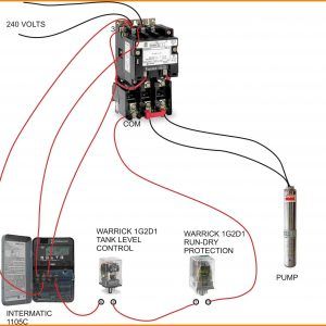
240 volt contactor wiring diagram. If not the arrangement won t function as it ought to be. Many large pieces of equipment are powered directly from high voltage lines. The contactor has a 24 volt relay when this 24 volt relay is energized from the thermostat a call for cooling the contacts on the contactor close making a high voltage 220 240 connection to your compressor and outdoor fan causing the outdoor unit to come on.
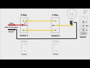
Each part should be set and connected with other parts in particular way. 240 volt contactor wiring diagram 220 volt contactor wiring diagram 240 volt coil contactor wiring diagram 240 volt contactor wiring diagram every electrical arrangement consists of various distinct pieces. Each part should be set and connected with different parts in particular way.
240 volts ac and 480 volts ac are commonly used for these large pieces of. If not the arrangement will not work as it should be. How to wire a contactor.
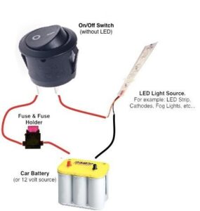
With this sort of an illustrative manual you are going to have the ability to troubleshoot stop and total your tasks without difficulty. 240 volt contactor wiring diagram 220 volt contactor wiring diagram 240 volt coil contactor wiring diagram 240 volt contactor wiring diagram every electric structure is made up of various different parts. My electrical wiring project involves wiring a 240volt motor.
Variety of 240v motor wiring diagram single phase. With this kind of an illustrative guidebook you will be capable of troubleshoot prevent and complete your projects without difficulty. What do the l1 l2 and t1 t2 wiring diagram abbreviations mean when wiring an electrical motor.
These lines far exceed the 120 volts ac standard in most homes. I am trying to run power to a 240volt electrical motor i bought but i do not know what the abbreviations mean and how to read the diagram that came with the new motor. 240 volt contactor wiring diagram you will need a comprehensive professional and easy to know wiring diagram.
There are several types of contactors that we sell. Wire a 240 volt motor electrical question. Wiring diagram book a1 15 b1 b2 16 18 b3 a2 b1 b3 15 supply voltage 16 18 l m h 2 levels b2 l1 f u 1 460 v f u 2 l2 l3 gnd h1 h3 h2 h4 f u 3 x1a f u 4 f u 5 x2a r.

4 Wire 240 Volt Wiring Diagram Electrical Wiring Diagram Electric Motor Motor

Single Phase Motor Wiring With Contactor Diagram Electrical Online 4u Circuit Diagram Electrical Circuit Diagram Electrical Diagram

Ac Relay Which Is Com Wire Elegant In 2020 Electrical Symbols Wire Electrical Wiring Diagram

240v Motor Wiring Diagram Single Phase Collection Single Phase Motor Wiring Diagram With Capacitor Electrical Diagram Electric Motor Electrical Circuit Diagram

Capacitors For Compressor Wiring Diagram Ac Capacitor Electrical Circuit Diagram Diagram

Hvac Relay Wiring Diagram New Diversitech Transformer T1404 Wiring Diagram Ecourbano Serverf Basic Electrical Wiring Electrical Circuit Diagram Circuit Diagram

Contactor Wiring Diagram With Timer Diagram Diagramtemplate Diagramsample Timer Wire Diagram

3 Wire Submersible Well Wiring Diagram Get Free Electrical Circuit Diagram Circuit Diagram Capacitors

Single Phase Submersible Pump Starter Wiring Diagram Gooddy Org Best Of Submersible Pump Submersible Submersible Well Pump

Wiring Diagram For 220 Volt Single Phase Motor Bookingritzcarlton Info In 2020 Diagram Electricity Wire

24 Volt Vs 240 V Coil Contactor Wiring Diagram Air Conditioner Contactor Diagram Design Air Conditioner Pole

Contactor Timer بحث Google Timer Electricity Graphic Card

Contactor Wiring Diagram With Timer New 240 Volt Hvac Wiring Wiring Diagram Write House Wiring House Wiring Basics Home Electrical Wiring

Single Phase Motor Contactor Wiring Diagram Elec Eng World Electrical Wiring Electrical Engineering Electricity

Single Phase Motor Wiring With Contactor Diagram Circuit Diagram Electrical Circuit Diagram Electrical Wiring Diagram

24 Volt Vs 240 V Coil Contactor Wiring Diagram Air Conditioner At Electrical Circuit Diagram Circuit Diagram Auto Transformer

Wiring Diagram Book File 0140 Ing

Photo Of Single Phase Wiring Diagram For House Three Phase Wiring Rh Electronicshub Or In 2020 Electrical Wiring Diagram Air Compressor Pressure Switch Circuit Diagram

3 Phase 240v Motor Wiring Diagram Electrical Circuit Diagram Circuit Diagram Auto Transformer