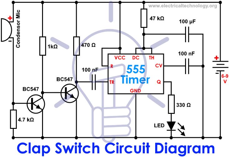
It was invented by R Carlile Stevens and E Dale Reamer on 20th February 1996. You can see the circuits and connections in the above schematic diagram of clap switch.
Pin On Electronica Proyectos Faciles
The main advantage of this technology is that it is mainly helpful for a mobility-impaired person.

Switch Circuit Diagram. An electronic device that can control light appliances by users clap action is a clap switch. Single-Pole SP Double-Pole DP Switch Wiring Diagrams Diagrams represent both momentary contact or maintained contact switches. Light before switches power at light fitting.
A set of as built prints and instructions manuals covering the switchboards are. It consists of symbols to represent the components and lines to represent. Wiring a Single Pole Switch Source.
Now in the diagram above The power source is coming in from the left. Switches with Two Pilot Lights SPST Off-On Dependent Independent Four terminals SPDT On-Off-On of On-On dependent Four terminals SPDT On-Off-On or On-On Independent Four terminals Diagram H Diagram J Diagram K B L 2 4. This simple diagram below will give you a better understanding of what this circuit is accomplishing.
Following are some practical illustrations of the light switch wiring to make our minds and concepts more precise about what we have seen above. Initially the transistor is in OFF state because there is not enough 07v base-emitter voltage to turn it ON. 3 Way Switch Circuit Diagram.
The electricity source and light fixture are connected to the same switch. Wiring Diagram For 3 Way Switch With Multiple Lights Http Bookingritzcarlton Info Wiring D Installing A Light Switch 3 Way Switch Wiring Dimmer Light Switch. The sender and receiver transmits communication signals to request and acknowledge establishment of circuits.
To turn the PNP transistor operating as a switch ON the Base terminal is connected to ground or zero volts LOW as shown. This diagram illustrates wiring for one switch to control 2 or more lights. Phases of Circuit Switch Connection Circuit Establishment.
Multiple receptacle outlets can be connected with lighting outlets as depicted in the above light switch wiring diagram. The above light switch wiring diagram depicts the power from the circuit breaker panel going to an electrical receptacle outlet and then continues to the next outlet and then to a single pole wall switch and then to another outlet. This is PNP and NPN amplifier circuit diagram.
The Black Wire – Power In source attaches to one of the switch screw terminals. Circuit Diagram Its Working. Not only will it help you attain your required final results.
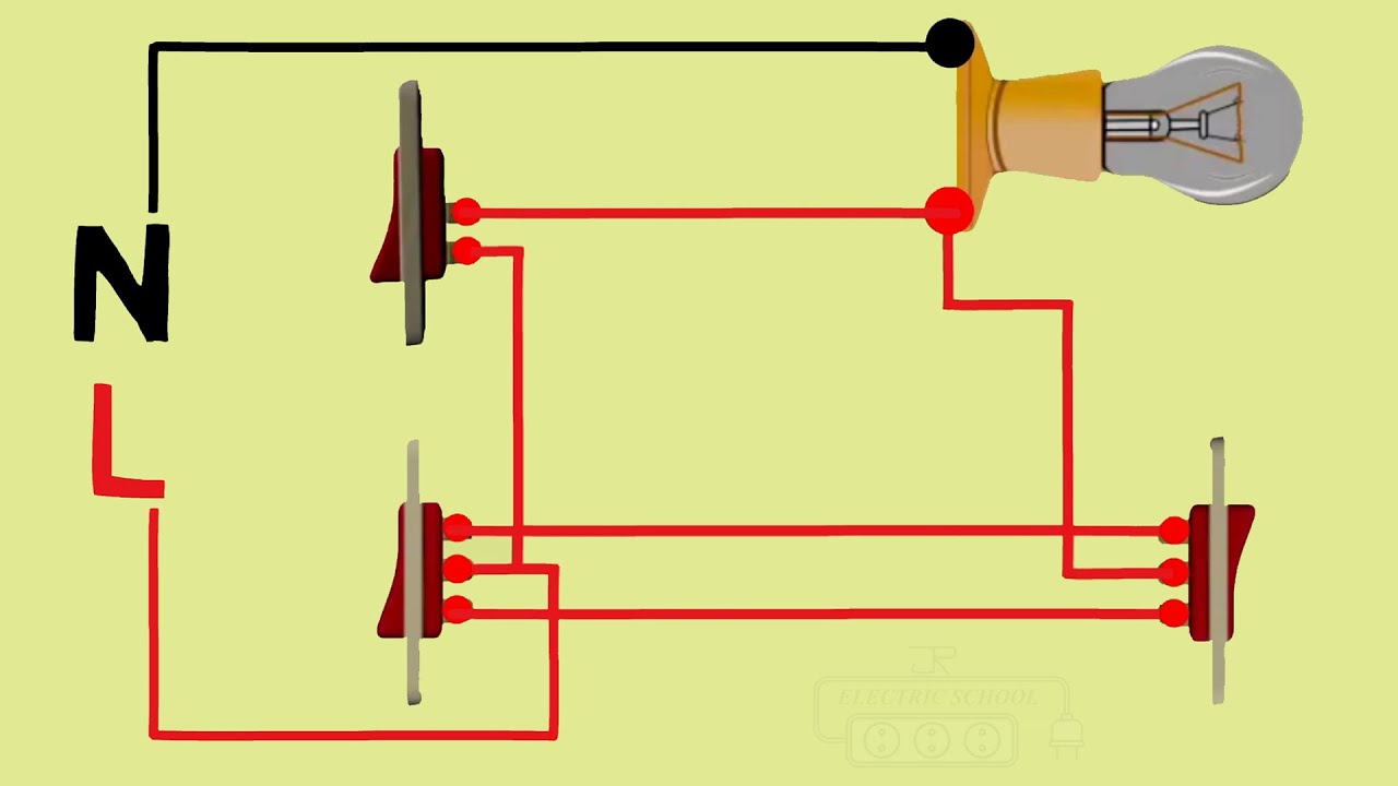
Measure voltage across the battery across the switch. PIN1 of both the switches are connected with the phase or live wire and PIN2 of both the switches are connected with the one end of the lamp. You can use tools or colors to label the different types of wires used and used different line styles.
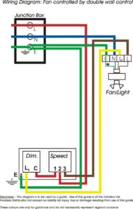
What is a Clap Switch. Electrical switch wiring diagram You will need a comprehensive skilled and easy to know Wiring Diagram. Twinearth from the ceiling rose to the first switch and three wires between the switches usually 3 core and earth cable.
Circuit electrical wiring enters the switch box. It is really simple to attract a wiring diagram. Switch wiring shows the Power Source Power In starts at the switch box.
The dotted box C is the electronic switching circuit and the dotted box D is the battery charging current limiting circuit. DESIGNATES EXTERNAL JUMPER PROVIDED BY CUSTOMER 1 V-Series Contura Switches Standard Switch Circuit Diagrams NOTE. In this diagram the electrical source is at the first switch and the light is located at the end of the circuit.
CIRCUIT DIAGRAM 2 6 6 6 6 6 6 G CIRCUIT DIAGRAM 7 2 2 5 2 5 CIRCUIT DIAGRAM SYMBOL LEGEND DESIGNATES TERMINALS AND CONTACTS. OHNSONVENUEs0LAINVILLE 4 n s0HONE n sAX n. In a PNP transistor output current flows from the emitter to the collector.
This is the new ebay. The hot and neutral terminals on each fixture are spliced with a pigtail to the circuit wires which then continue on to the next light. Bare copper Ground.
Fixture wiring exits the switch box. The dotted box B is the battery charging linear voltage regulated circuit. This circuit is most impressive when the wires are long as it shows how the switch is able to control circuit current no matter how physically large the circuit may be.
Npn transistor switching circuit diagram. With such an illustrative guide you will be able to troubleshoot avoid and full your projects without difficulty. In the below wiring diagram the phase line is connected parallel to the light switch and the plug socket switch.
Ad Over 70 New. 2 Simple Automatic Transfer Switch Ats Circuits Homemade Circuit Projects. Rcd Switchboard Wiring Diagram.
And the point A is at high potential and point A is connected to Trigger pin 2 of 555 IC as a result Trigger pin 2 is also at high potential. 3-Way Switch Wiring Diagram NM Cable A very common type of 3-way electrical diagram is when the power supply wire moves from one switch to the second switch and finally terminates at the fixture. The source is at SW1 and 2-wire cable runs from there to the fixtures.
In this phase a dedicated circuit is established from the source to the destination through a number of intermediate switching centres. Explanation of Wiring Diagram 1. Find Wiring Diagrams Switches now.
1 Other circuits available. Light after switches power at the switch. April 16 2020 Wiring Diagram.
Automatic change over switch changeover circuit diagram of an manual wiring with timer 3p 630a ats generator relay china transfer zenith abb 3 4 pole 6 2 simple phase ats5070 17 000 watt home standby how to wire a your stratton power products 040401 01 changes installations 10. Three way switching 3 wires. Build a one-battery one-switch one-lamp circuit as shown in the schematic diagram and in the illustration.
Angelo on September 24 2021. Ad Templates Tools Symbols For Any Circuit Diagram Or Design. The parts in the dotted box A constitute the battery starting and shutdown circuit.
When wiring a 2-way switch circuit all we want to do is to control the black wire hot wire to turn on and off the load. 3 Way Switch With Power Feed Via The Light Multiple Lights Home Electrical Wiring Electrical Wiring Light Switch Wiring. 14 Pnp Transistor Circuit Diagram.
The electricity source and light are in between switches. As you can see in the Schematic Diagram of 2 way switch circuit below the common of both the switches are short-circuited. This wiring diagram shows both switches aligned together with the fixture at the end.
The other end of the Lamp is connected with the Neutral line of AC power supply.

Circuit Diagram Circuit Diagram Switch Circuit

How To Use Relay In A Circuit Circuit Electronics Circuit Circuit Diagram

Proximity Switches Circuit Diagram Operation Instrumentation Tools Proximity Switch Circuit Circuit Diagram

The Page Coolly States An Uncomplicated Triac Dimmer Switch Circuit That Can Be Put Togeth Dimmer Switch Electronic Circuit Projects Electrical Circuit Diagram

Light Activated Switch Circuit Using Ldr Sensor Ldr Sensor Circuit Design Circuit Diagram

How To Make Simple Clap Switch Circuit Working Circuit Diagram Electronic Engineering Electronics Design

Clap Switch Circuit Electrical Circuit Diagram Electronic Circuit Projects Circuit

Pin On Circuits
Master On Switch Wiring Diagram In Two Way Switch Youtube Basic Electrical Wiring Electrical Circuit Diagram Home Electrical Wiring

Example Of How To Use A Micro Switch Electronic Circuit Design Switch Micro
Touch On And Off Switch Circuit Diagram And Working Circuit Diagram Electronic Schematics Domestic Wiring

Touch On And Off Switch Circuit Diagram And Working Circuit Diagram Electronics Basics Electronic Schematics

Day Night Automatic Triac Switch Circuit Electronic Circuit Design Electronics Mini Projects Electronics Projects Diy

Infrared Ir Remote Control Switch Circuit Diagram Remote Control Electronic Circuit Projects Remote

Pin On Brownies

How To Make Simple Clap Switch Circuit Working Circuit Diagram Circuit Power Supply Circuit

Simple Automatic Day Night Switch Circuit Diagram Circuit Diagram Circuit Circuit Projects

Temperature Sensor Relay Switch Circuit Circuit Relay Sensor

3 Way 2 Circuit Switches Electrical Switches Lamp Switch Electrical Circuit Diagram