The circuit incorporates relays along with other components such as switches motors timers actuators contactors etc. Well since I had an idea but wasnt 100 sure I did some reading and de.
Wiring Diagram 4 Pin Relay Fitfathers Me Fancy At Relay Wiring Diagram 4 Pin Relay Automotive Electrical Electrical Diagram
The ML-ACR Automatic Charging Relay and ML-RBS Remote Battery Switch when paired offer complete battery management of large battery banks with the push of a button.

Basic Relay Wiring Diagram. Wiring Diagram For Automotive Relay Wiring Diagram Line Wiring Diagram. A car wiring diagram is a map. It consists of a coil of wire surrounding a soft iron core an iron yoke which provides a low reluctance path for magnetic flux a movable iron armature and a set or sets of contacts.
Line diagrams also called schematic or elementary dia-grams show the circuits which form the basic operation of the controller. 55 New Potential Relay Wiring Diagram- A govern relay is used in the automotive industry to restrict and regulate the flow of electricity to. RC – Red Wire Power 24 Vac RH or 4 – Red Wire Jumpered Power 24 Vac W – White Wire For Heating Enable Y – Yellow Wire For Cooling Enable G – Green Wire Controls Fan ON-Auto.
Home Mobile Electronics Basics Relays Relay Wiring Diagrams Dozens of the most popular 12V relay wiring diagrams created for our site and members all in one place. Relay can be the best option to control electrical devices automatically. Remote Start Relay Diagram – Basic Only Relay Wiring Diagram.
Dozens of the most popular 12V relay wiring diagrams created for our site and members all in one place. Print the electrical wiring diagram off and use highlighters in order to trace the routine. Is a typical wiring diagram for a three-phase mag-netic starter.
The transistor allows the HC11 to control the medium sized coil current of relay. This video is presented by Edify Offroad this video covers basic relay operation as well as a simple wiring diagram for wiring two lights to a switch while. The flasher unit requires 2 x 21W 5W indicator bulb to work correctly.
This diagram was designed for 12 volt systems but can also be used for 6 volt systems. Published by means of Tops Stars Team on December 7 2013. Relay Switch Circuit Diagram Working of the Basic 5V Relay Circuit.
Basic schematic circuit diagram of Relay. First figure out the amperage of your electrical component. The basic Heat AC System thermostat typically utilizes only 5 terminals.
They do not indicate the physical relation-. The above diagram will give you an at a glance idea of how a tractor is wired up. The diagram here shows how a basic 4-wire thermostat is connected as indicated by the color code chart below.
This is the most basic type of switch the OnOff rocker switch as shown using Ozniums Black Anti Vandal Toggle Switch mounts in 16mm or 19mm hole. Basic race car wiring diagram. The following schematic shows the basic circuit.
If you need a relay diagram that is not included in the 76 relay wiring diagrams shown below please search our forums or post a request for a new relay diagram in our Relay. Clipsal Neon Indicator Wiring Diagram wiring diagram is a simplified tolerable pictorial representation of an electrical circuit. 12 Volt Wiring Diagram Circuit Diagram Camper Repair Zig.
Connect the relay with HC11 port pins this is used to control on switches. At the initial condition when switch is open no current flow through coil hence Common Port of relay is connected to NO Normally Open Pin so the. Actually we have been noticed that drag race car wiring diagram is being one of the most popular field at this time.
4 pin normally open relay with the switch on the negative side of the control circuit. The diagram above is the 5 pin relay wiring diagram. In this example we are simply turning on a light.
Scroll down and find the car radio wiring guide you need. There are different kinds of relays for different purposes. Wiring a 2 way switch on and basics learn sparkfun com how to wire smart basic diagram scientific two one gang multiway standard single pole light hometips overview of switches technical guide for omron automation home best decoration world class simple relay circuit function carlingtech 3 electrical template with concepts test equipment electronics.
Output positive input for horn lights with ac led 6 f switch kit interlocking holder 14 hot spst volt fuse remote start basic only unique bargains car 2pcs industry 2x 95. 12 Volt System Vintage Trailer Talk Electrical wiring This diagram was designed for 12 volt systems but can also be used for 6 volt systems. On Basic Relay Wiring Diagram.
4 pin normally open relay with the switch on the positive side of the control circuit. With their IP67 rating and 12V operating voltage they can be used in a wide range of application. Ro 1140 Basic Car Wiring Diagram Honda Fit.
A simple electromagnetic relay is an adaptation of an electromagnet. I need wiring diagram color code to wire a jvc model no. An ONOFF switch is added for the switching purpose of the relay.
The purpose of a relay is to automate. 12v Relay Wiring Diagram 5 Pin Relay Fuse Box Diagram. 12v Latching Relay Wiring Diagram.
Basic 12 Volt Wiring Diagram wiring diagram is a simplified pleasing pictorial representation of an electrical circuitIt shows the components of the circuit as simplified shapes and the gift and signal friends amongst the devices. If you need a relay diagram that is not included in the 76 relay wiring diagrams shown below please search our forums or post a request for a new relay diagram in our Relay Forum. This diagram will show you how simple it is to control motors lights valves other relays and any type load you want.
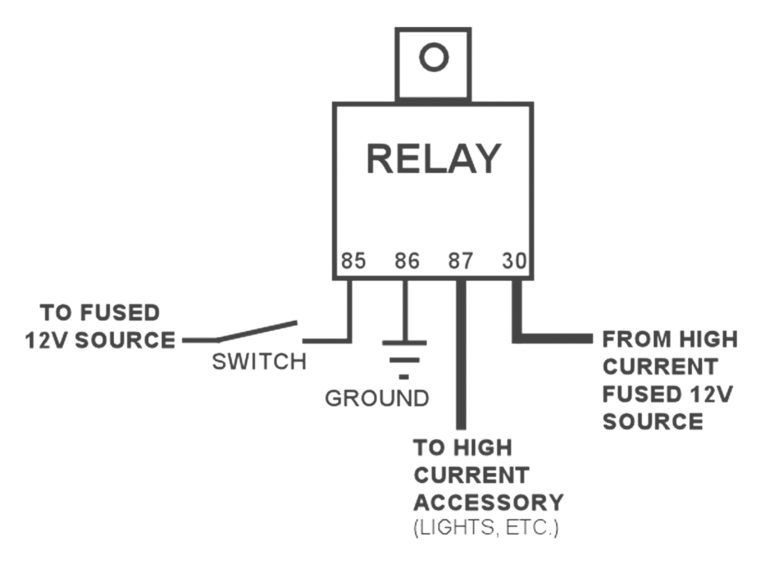
BASIC RELAY WIRING BRAKE SWITCH RELAY WIRING pink red black orange to brake switch non-hot side to a good chassis ground to turn signal switch brake feed in wire white on GM column or direct feed to brake lights when not routing through turn signal switch red black to a good chassis ground h e a d l i g h t s i w t c h remove existing dimmer feed wire yellow or blue. Wiring Diagram is a technique for describing configuration of electrical equipment installation for example installation of electrical equipment in substation in CB from panels to CB boxes which include aspects of telecontrol telesignaling telemetry all aspects that require a wiring diagram which is used to locate faults add equipment new auxillary etc. In the above circuit 5V relay is powered by a 9V battery.
Lets say were using household voltage in this circuit which is 110120 Vac. 5 pin is compromised of 3 main. The relay logic control works efficiently to perform basic ONOFF operations by opening or closing the relay contacts but it.
By looking at the diagram below we can go through the basic concept of a relay and how they operate. A few people have asked what gets connected to the different connectors on a relay. Relays Wiring 101 Basically a relay is an electrically operated remotely controlled switch.
Sample Wiring Diagrams for a Normally Open Relay Example 1. Wiring Diagram Line We are make source the schematics wiring diagrams and technical photos. The diode prevents relay from arcing by giving a return path for the energy stored in the magnetic field of coil.
Typical Wiring Diagram Line diagrams show circuits of the operation of the controller. This is a device consisting of a coil of wire wrapped around an iron core. It can be used for various switching.
Relay logic basically consists of relays wired up in a particular fashion to perform the desired switching operations.

12vdc Relay Wiring Diagram 4 Pin Relay Wiring Diagram Horn Diagram Relay Electrical Diagram

Bosch Relay Wiring Collection Circuit Diagram Relay Diagram

Relay Wire Diagram 5ab7826eea718 In 12 Volt Relay Wiring Diagram Electrical Circuit Diagram Circuit Diagram Electrical Diagram

Air Conditioner C S R Wiring Diagram Compressor Start Full Wiring Fully4 Air Conditioner Maintenance Refrigeration And Air Conditioning Hvac Air Conditioning

16 Motorcycle Horn Relay Diagram Car Horn Motorcycle Wiring Electrical Diagram

30 Unique Headlight Relay Wiring Diagram Electrical Wiring Diagram Electrical Circuit Diagram Relay

Great Wiring Diagram For Horn Relay Horn Relay Simple Wiring Car Horn Electrical Diagram Diagram

Starter Wiring Help Electrical Circuit Diagram Electricity Wire

5 Pin Wiring Diagram Electrical Diagram Electrical Circuit Diagram Trailer Wiring Diagram

12v Changeover Relay Wiring Diagram Auto Beautiful 12 Volt Ansis Throughout 12v In 12 Volt Relay Wiring Diagram Circuit Diagram Relay Diagram

30 Unique Headlight Relay Wiring Diagram A Control Relay Is Used In The Automotive Industry To Restrict And C Electrical Wiring Diagram Relay Electronic Parts

Simple Relaycircuit Is An Electrically Operated Switch Many Relays Use An Electromagnet To Me Automotive Electrical Automotive Repair Basic Electrical Wiring

12 Volt 5 Pin Relay Diagram Electrical Circuit Diagram Circuit Diagram Electrical Diagram

50 Luxury 90340 Relay Wiring Diagram Thermostat Wiring Electrical Circuit Diagram Electrical Wiring Diagram

50 Fresh 12 Volt Relay Wiring Diagram Electrical Circuit Diagram Electrical Wiring Diagram Trailer Wiring Diagram
60 New 87a Relay Wiring Diagram Relay Basic Electronic Circuits Electronic Circuit Projects

Best Bosch Relay Wiring Diagram 5 Pole Electrical Outlet Symbol 2018 Electrical Circuit Diagram Light Switch Wiring Electrical Wiring Diagram

45 Beautiful 5 Pin Relay Wiring Diagram Car Horn Electrical Wiring Diagram Automotive Electrical

Bosch Relay Wiring Diagram Elegant Electrical Circuit Diagram Circuit Diagram Electrical Diagram