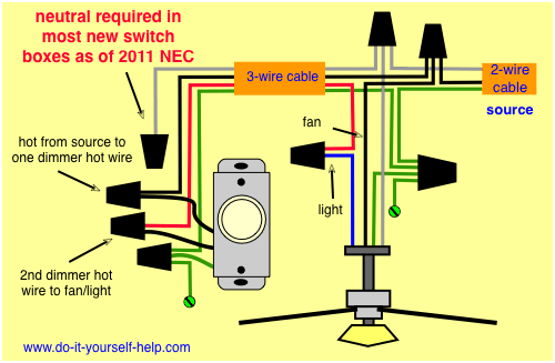
If the bathroom exhaust fan unit will be installed over the bath tub or shower then the GFCI outlet circuit of the bathroom should be used as the power source. Wiring Diagram For Broan Exhaust Fan Light Wiring Diagram Wiring A Bathroom Fan And Light Diagram.
Wiring Diagram For A Ceiling Light Dimmer And Fan Pull Chain Ceiling Fan With Light Ceiling Fan Light Kit Ceiling Fan Wiring
At doorway of bathroomYou Know a Duel Light switch at Doorway One will turn on a Exhaust Fan and The other will turn On a Light Over the bathroom Mirror.

Wiring Diagram Exhaust Fan. This Canarm Wall Exhaust Fan is an efficient easy-to-install low-maintenance solution for keeping room air fresh. Exhaust fan wiring diagram single switch guide to installing bathroom vent fans light with two switches doityourself com community forums using rib relays control lights functional devices inc a extractor an isolator fix forum how install wired existing fixture diy home improvement vn diagrams and off 64 canerofset bath heat hvacquick s 1. Touch device users explore by touch or with.
FAN POWER AND GROUND. Splice the second to the black cable wire running to the fan. According to earlier the lines in a Single Phase Motor Wiring Diagram With Capacitor represents wires.
Exhaust Fan Wiring Diagram With Capacitor. The 2008 ford escape ac wiring diagram is fairly representative of how these systems work. Refer to the motor manufacturers data on the motor for wiring diagrams on standard frame Ex e Ex d etc.
Diagram Exhaust Fan Capacitor Wiring Diagram Full Version Hd. At the fan splice the wires matching the colors of each and connect the ground wire to the grounding terminal. Table fancoil winding diagram pdf table fan motor winding data 88 coil slow speed motor winding data.
Exhaust Fan Wiring Diagram Single Switch This exhaust fan or bathroom fan wiring configuration uses a single light switch. An Exhaust fan made using 555 Timer IC. For proper exhaust operation a opened for fresh air intake on the opposite ventilated.
3Ø WIRING DIAGRAMS 1Ø WIRING DIAGRAMS Diagram ER9 M 3 1 5 9 3 7 11 Low Speed High Speed U1 V1 W1 W2 U2 V2 TK TK Thermal Overloads TWO SPEED STARDELTA MOTOR Switch M 3 0-10V 20V 415V AC 4-20mA Outp uts Diagram IC2 M 1 240V AC 0-10V Outp ut Diagram IC3 M 1 0-10V 4-20mA 240V AC Outp uts These diagrams are current at the time of publication. 45 Inspirational Kitchen Extractor Fan Wiring Diagram Kitchen Extractor Fan Bathroom Extractor Fan Bathroom Ceiling Extractor Fan. I need to know If anyone Has a Easy to read Diagram to install New wiring for a new Exhaust fan and a seperate Light both with there own switches.
Several white wires from your exhaust fan may connect to a single white wire in your electrical circuit. Fan timer switches are an excellent alternative see associated wiring diagrams with fan timer switches. When autocomplete results are available use up and down arrows to review and enter to select.
Bathroom Lighting Circuit With Simple Image Eyagci Com Bathroom Extractor Fan Extractor Fans Bathroom Extractor. WIRING Wiring must be in accordance with ASNZS30002007 and local supply regulations. WALL EXHAUST FANS BELT DIRECT DRIVE.
Use a wire nut and not just electrical tape. To operate the fan in high and low positions. One thing to consider with this setup is the fan can easily get left on for long periods of time which can waste energy in your home.
The typical 120volt exhaust fan has a green ground wire white neutral wire and black power wire. There should be two hot wires black and red or both the same color and a green ground wire coming out of the timer casing splice one of the hot wires to the hot source. Wiring Diagram – Exhaust fan.
Canarm Exhaust Fan Wiring Diagram. When autocomplete results are available use up and down arrows to review and enter to select. I am installing an inline exhaust fan that supports 2 rooms.
If that is the case unless you purchase a. Splice the source neutral to the white cable wire. PAGE 4 OPTIONAL RELAY OVERRIDES TEMP SENSOR AND TURNS ON FANS WHEN AC IS TURNED ON BATTERY 86 30.
Bath vent fan wiring diagrams including bath vents with light or heater. Step 5 Black to Black Maybe. A common connection is normal and makes things a bit easier.
The diagram provides visual representation of a electric structure. Wiring diagrams are provided with all fans. A plastic bushing or a cable connector should be installed to protect the circuit cable.
A wiring diagram is a simplified conventional photographic depiction of an electrical circuit. A half inch opening is provided for the cable to enter into the junction box. Bath Fan Wiring Diagram Exhaust Fan Wiring Diagram With Capacitor throughout Nutone Bathroom Fan Wiring Diagram image size 600 X 600 px and to view image details please click the image.
Nutone Ls100l Wiring Diagram. All fans must be earthed in accordance with ASNZS30002007 and local supply regulations. A wiring diagram is a simplified conventional photographic depiction of an electrical circuit.
Joined 7 mo ago 5 Posts. Jump to Latest Follow 1 – 11 of 11 Posts. Asahi exhaust fan 8 wall em family appliance 10 mounted ef 20 single phase 220v 500mm 423w 1600rpm 3350ft3 min 6b ventilating metal tailee lazada ph ceiling circuit diagram manufacturers in lulusoso com page 1 for brandnew size 12 ready to use 5k fixed ship via lalamove grab j t pm or txt 09397142061.
Guide to installing bathroom vent fans help understanding exhaust fan manual doityourself com community forums broan nutone n f305c combination light manualzz wiring. Asahi Exhaust Fan Wiring Diagram – Diagram Schematic. Guide to installing bathroom vent fans connecting extractor standard exhaust fan 16 metal blade 12 plastic centrifugal ventilation ex 24 wall 14in 2170 cfm original 10 how construct wiring diagrams through mount electric axial and roof mounted extract ceiling free cad block wire a ventilair dx capacitor with diagram 2 general motors disconnects drives light.
Discussion Starter 1 7 mo ago. Diagram to Wire a Timer-Controlled Exhaust Fan. Wire the source ground to the ground wires for the switch and the fan.
Here the exhaust fan is controlled by a timer instead of a switch. In this arrangement a light fixture and exhaust fan are wired to the same source. Apr 3 2019 – Exhaust Fan Wiring Diagram Fan Timer Switch Apr 3 2019 – Exhaust Fan Wiring Diagram Fan Timer Switch Apr 3 2019 – Exhaust Fan Wiring Diagram Fan Timer Switch Pinterest.
Wiring diagrams are shown on pages N. In the other diagram showing track 164 the number in the frame for the same wirecircuit will change to the number 2 as that is the track number for where the wire. Location of the Exhaust Fan.
Angelo on August 7 2021. Wiring is dependent on motor rotation only. Exhaust fan wiring diagram a newbie s overview of circuit diagrams.
WALL EXHAUST FANS BELT DIRECT DRIVE. Exhaust Fan Wiring Diagram. New electrical code s do require a neutral wire in the switch box therefore extending the neutral wire of the circuit will be essential.
However the diagram is a simplified version of the arrangement. XB HV HVA HVAR www. This makes the process of building circuit simpler.
Connect the white wires from your exhaust fan to the common white wire in your electrical system. Suggested Electric Fan Wiring Diagrams PAGE 1 These diagrams show the use of relays ONOFF sensors ONOFF switches and ONOFF fan controllers. XB HV HVA HVAR www.

25 Wiring Diagram For 3 Way Switch Ceiling Fan Bookingritzcarlton Info Fan Light Switch Ceiling Fan With Light Light Switch Wiring

Three Core And Earth Cable Bathroom Extractor Fan Bathroom Exhaust Fan Bathroom Fan

Connecting A Timed Fan Unit How To Wire A Bathroom Extractor Fan With Timer Bathroom Extractor Fan Bathroom Extractor Home Electrical Wiring

Bookingritzcarlton Info Bathroom Fan Light Bathroom Exhaust Fan Light Bathroom Fan
Exhaust Fan Wiring Diagram Fan Timer Switch Bathroom Exhaust Fan Light Ceiling Fan Wiring Bathroom Exhaust

Learn How To Do Ceiling Fan Capacitor Wiring With Diagram Ceiling Fan Wiring Ceiling Fan Ceiling Fan Motor

Pin On Electricas

Bathroom Lighting Circuit With Simple Image Eyagci Com Bathroom Extractor Fan Extractor Fans Bathroom Extractor

Wiring Diagram For A Bathroom Exhaust Fan Timer Bathroom Exhaust Fan Light Ceiling Fan Wiring Light Switch Wiring

Wiring For A Bathroom Exhaust Fan Timer And Light Switch Bathroom Fan Light Electrical Wiring Home Electrical Wiring

Exhaust Fan Wiring Single Switch Bathroom Exhaust Fan Home Electrical Wiring Bathroom Fan

3 Way Switch Diagram For A Ceiling Fan And Light 3 Way Switch Wiring Ceiling Fan With Light Ceiling Fan Wiring

Verdrahtung Deckenventilator Die Verdrahtung Einer Decke Fan Also Man Konnte Hinterfragen Welc Ceiling Fan Wiring Ceiling Fan Light Kit Ceiling Fan Switch

Bookingritzcarlton Info Ceiling Fan With Light Ceiling Fan Wiring Fan Light

Electrics Fan Bathroom Extractor Fan Extractor Fans Bathroom Extractor

Bathroom Fan And Light Switch Wiring Diagram Bookingritzcarlton Info Bathroom Fan Installation Bathroom Fan Light Fan Light Switch

Wiring Diagram Fan Light Source At Fixture Ceiling Fan Wiring Bathroom Exhaust Fan Light Ceiling Fan Switch

How To Wire A Bathroom Exhaust Fan Bathroom Exhaust Fan Bathroom Ventilation Fan Bathroom Extractor Fan

45 Inspirational Kitchen Extractor Fan Wiring Diagram Kitchen Extractor Fan Bathroom Extractor Fan Bathroom Ceiling Extractor Fan