Pertronix Ignitor 2 Wiring Diagram. Connect the ignitor red wire to the positive (+) side of the ignition coil. The wiring diagram shown below is modeled after one obtained from pertronix.
Pertronix Ignitor 2 Wiring Diagram For Your Needs from www.dentistmitcham.com
Dwell angle is increased or decreased with changing engine. For optimum performance purchase and install the. Ok so i misplaced my diagram for the connections of the ignitor and.
You must connect the resistor connectors together, then hook the original coil wire to the coil, and the pertronix to the coil + otherwise, you won't get start voltage, known on. Pertronix ignitor wiring diagram iii ballast resistor manual. Pertronix 91181 ignitor® ii delco 8 cyl electronic ignition conversion kit.
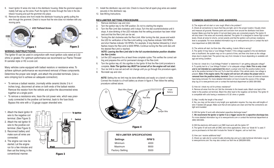
The Ignitor Ii Ignition Can Be Used In Conjunction With Most Ignition Coils Rated At 0.45 Ohms Or Greater.
Diagramweb.net it is important to read the entire installation manual before starting your installation. Pertronix ignitor 1168ls user manual | page 2 / 2. A bracket from aluminum sheet.
The Wiring Diagram Shown Below Is Modeled After One Obtained From Pertronix.
Learn more lowest price guarantee add to cart pertronix 91544. Adaptive dwell maintains peak energy throughout the entire rpm range, reducing misfires while improving. Connect the ignitor red wire to the positive (+) side of the ignition coil.
Attach Positive (Red) Lead Of Your Voltmeter To The Positive.
8 pics about a bracket from aluminum sheet about 2 wide to wrap around the square : 14 pics about pertronix ignitor wiring diagram : 1984 chevrolet distributor electrical wiring flamethrower coil wiring diagram.
The Pertronix Unit Needs A 12 Volt Power Source.
Pertronix technical support () www. The coil power wire is resistor wire. We recommend the factory spark.