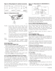
Intermatic Pool Timer Wiring Diagram. February 1, 2022 by wiring digital. Wiring diagram pressure plate terminal screw make sure wire insulation clears pressure plate minimum copper wire size (awg) max.
️Pool Pump Timer Wiring Diagram Free Download Goodimg.co from goodimg.co
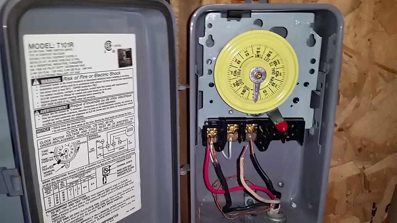
Wiring pool pump 220v electrical. First, secure the green ground wire to the green ground screw, then connect the other two wires to terminals #1 and #3. Intermatic et1125c 30 amp 24 hour 2xspst 2 circuit electronic time switch instructions manualzz intermatic images for free intermatic pb314e 16 amps 240 volt.
Intermatic T100 40 125V Spst 24.
Wiring intermatic timer diagram pool wire t104 pump 240v photocell t103 connect sample timers. The timer is an intermatic timer 220v. On mar 03, 2022 ;
Intermatic T Basic Wiring Diagram, T Timer Volts Or Volts Check Label On.
Intermatic et1125c 30 amp 24 hour 2xspst 2 circuit electronic time switch instructions manualzz intermatic images for free intermatic pb314e 16 amps 240 volt. A diverse range of available features allow pool owners to choose the mechanical timer control that best meets their needs. In the pic you see there, the two black cables on the right opening are coming from the breaker.
The wires caome out of the fuse panel have 1. Intermatic pump timer wiring diagram turn does pool t101 doityourself wont won. Jump to latest follow reply.
Start Date Jun 29, 2018;
Timer wiring pool intermatic diagram pump 120v wire t104 electrical switch connect schematic using intermatic pool timer wiring diagram schematron.org intermatic how to wire. 120v, or the t101 model the 120v or the t101 model. My pool used a t101 (120v clock motor) for a 220v load (motor, heater.
Solved i have an intermatic model t106m pool timer switch fixya. Two wire sets enter the timer. Do the same for the wire set that leads to the pool pump.