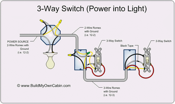
With a three way switch three wires connect the pair of switches two black traveler wires and a third common wire. A wiring diagram is a streamlined conventional pictorial depiction of an electrical circuit.

3 Way Switch Wiring Diagram Light Switch Wiring 3 Way Switch Wiring Light Switch
3 way switch wiring diagram with line and load in the same switch box.

3 way dimmer switch wiring diagram power at switch. In the diagram below a 2 wire nm cable supplies power from the panel to the dimmer box the black line wire connects to the common terminal of the 3 way dimmer a 3 wire nm connects the travelers of the dimmer to the travelers of the 3 way switch traveler wires are interchangeable on each switch. In the above diagram the white wire must be re identified as a hot wire at each switch location. Wiring a standard 3 way dimmer switch.
Attach to the bonded ground wire s in the switch box. The white wire becomes the energized switch leg as indicated by using black or red electrical tape. The following 3 diagrams show the wiring for a specially made dimmer that can be used in these circuits in place of either of the the 3 way switches or both.
This arrangement allows for lowering the lights in a 3 way circuit. When the circuit s power is turned on any of these may be hot depending upon how the switches are toggled. Assortment of leviton 3 way dimmer switch wiring diagram.
The white wire between switches is not being used as a neutral. It reveals the elements of the circuit as simplified forms as well as the power and also signal connections in between the tools. 3 way dimmer switches typically come with the following pre wired leads.
3 way dimmer switch wiring diagrams. The white wire of the cable going to the switch is attached to the black line in the fixture box using a wire nut. An example of three way switch wiring with the line and load in the same 4 square electrical box.
These wires attach to the travelers which are the pair of wires attached to the two screws at one end of the regular 3 way switch. 3 way switch diagram 2 above shows the electricity source starting at the fixture.

3 Way And 4 Way Switch Wiring For Residential Lighting Tom Remus Electric Light Switch Wiring Electrical Switches 3 Way Switch Wiring

Help With Wiring Two Way Light Cruisers Sailing Forums Light Switch Wiring Three Way Switch Electrical Wiring

Wiring 3 Way Dimmer With Source And Dimmer In The Middle Light Switch Wiring 3 Way Switch Wiring Wire Switch

3 Way Switch Wiring Diagram Light Switch Wiring 3 Way Switch Wiring Three Way Switch

How To Wire 3 Way Dimmer 3 Way Switch Wiring Dimmer Light Switch Light Switch Wiring

Typical 3 Way Dimmer Wiring Diagram 3 Way Switch Wiring Light Switch Wiring Dimmer Light Switch

3 Way Dimmer Basically The Same As Any Other Switch Dimmer Switch Dimmer 3 Way Switch Wiring

Wiring Diagram For 3 Way Switch With 4 Lights Http Bookingritzcarlton Info Wiring Diagram For 3 Way S Three Way Switch 3 Way Switch Wiring Electrical Wiring

Elegant Wiring Diagram Nz Diagrams Digramssample Diagramimages Wiringdiagramsample Wirin Light Switch Wiring Electrical Wiring Diagram 3 Way Switch Wiring

Wiring Diagram For 3 Way Switch Http Bookingritzcarlton Info Wiring Diagram For 3 Way Switch Light Switch Wiring 3 Way Switch Wiring Electrical Wiring

Wiring Diagram For 3 Way Switch With Multiple Lights Http Bookingritzcarlton Info Wiring Diagram Fo 3 Way Switch Wiring Three Way Switch Light Switch Wiring

Wiring Diagram For 3 Way Switch With 4 Lights Bookingritzcarlton Info 3 Way Switch Wiring Light Switch Wiring Dimmer Light Switch

3 Way Dimmer Switch For Single Pole Wiring Diagram Dimmer Switch Light Switch Wiring 3 Way Switch Wiring

Togglelinc Relay Insteon Remote Control On Off Switch Non Dimming White Smarthome Light Switch Wiring Dimmer Switch Ceiling Fan Wiring

3 Way Switch With Power Feed Via The Light Light Switch Wiring Home Electrical Wiring Electrical Projects

3 Ways Dimmer Switch Wiring Diagram Basic 3 Way Dimmers Switches A 3 Way Dimmer Switch Is Very Similar T Light Switch Wiring Dimmer Switch Ceiling Fan Wiring

Unique Wiring Diagram For A Leviton Dimmer Switch Diagram Diagramtemplate Diagramsample Light Switch Wiring 3 Way Switch Wiring House Wiring

3 Way Switch With Power Source Via The Light Switch How To Wire A Light Switch Electrical Switch Wiring Light Switch Wiring Three Way Switch

3 Way Switch Wiring Diagrams 3 Way Switch Wiring Home Electrical Wiring Wire Switch


