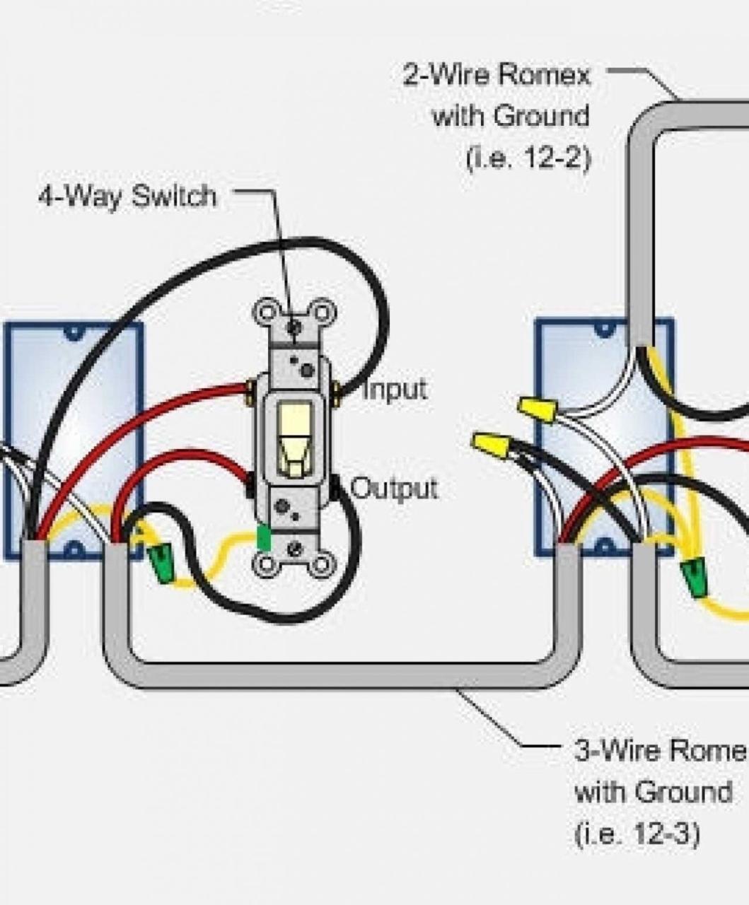
Accessory Relay Wiring Diagram . Aquastat honeywell hubs gulfstream argo sr501 manualzz. Wiring argo ir882 isolation relay.
So How Can I Test A Relay? from www.justanswer.com There are connectors at the near the gauge unit for an accessory outlet, gear position. Here we will only discuss the relay’s terminals. 16 pics about wiring diagram under voltage relay :
Source: www.justanswer.com
Novita rl45 relay wiring diagram diagramofwiring.blogspot.com. 16 pics about wiring diagram under voltage relay :
Source: apiccolisogni.blogspot.com
18 pics about how to wire a relay. Although you can choose a relay with factory installed wire leads relays have a standard wiring pattern which makes it possible for.
Source: strawberry-sweet.blogspot.com
There are connectors at the near the gauge unit for an accessory outlet, gear position. Wiring diagram under voltage relay.
Source: 2020cadillac.com
Accessory relay wiring diagram ford explorer v8 2005 electrical circuit wiring diagram. Wiring a relay with 2 distribution blocks (pic.
Source: www.pinterest.fr
For voltage sources utilizing a hot and a neutral line, the hot. Relay logic wiring relays wire light normally open circuit diagrams simple chapter function nc control input output power common ways.
Source: tonetastic.info
There are different kinds of relays for different purposes. 16 pics about wiring diagram under voltage relay :
Source: www.pinterest.com
In order to realize the function of the relay, you have to know its basic construction of it. Fuse duramax ob2 savana w4500 schematic relay schematron mustang.
Source: www.panoramaline.com
Wiring a relay with 2 distribution blocks (pic. The vulcan s has an optional accessory relay (about $20) that does exactly what you're looking for.
Source: schematron.org
Wiring diagram relay accessory offroaders relays intended using tips fuse box px. In order to realize the function of the relay, you have to know its basic construction of it.
Source: kelvin-okl.blogspot.com
Aquastat honeywell hubs gulfstream argo sr501 manualzz. Relay wiring diagram pump switch fuel horn wire hooking solenoid clutch heated hard panasonic ford 12v help need power shutoff.
Source: www.youtube.com
Relay can be the best option to control. Accessory relay wiring diagram userguidefixlynn.z21.web.core.windows.net.
Source: www.pinterest.com
The vulcan s has an optional accessory relay (about $20) that does exactly what you're looking for. Novita rl45 relay wiring diagram diagramofwiring.blogspot.com.
Source: diagramofwiring.blogspot.com
Accessory relay wiring diagram ford explorer v8 2005 electrical circuit wiring diagram. There are connectors at the near the gauge unit for an accessory outlet, gear position.
Source: www.pinterest.com
Wiring a relay with 2 distribution blocks (pic. There are connectors at the near the gauge unit for an accessory outlet, gear position.
Source: gramwir.blogspot.com
Iso 280 mini relay (4 pin) iso mini relay (5 pin) sample wiring diagrams for a normally open relay example 1. The vulcan s has an optional accessory relay (about $20) that does exactly what you're looking for.
Source: www.pinterest.com
Relays power relay diagram motor schematic. In order to realize the function of the relay, you have to know its basic construction of it.
Source: www.pinterest.com
Ideal for adding extra fans, horns and lights. Wiring argo ir882 isolation relay.
Source: www.pinterest.com
Iso 280 mini relay (4 pin) iso mini relay (5 pin) sample wiring diagrams for a normally open relay example 1. Besides, it helps you to draw a relay wiring diagram.
Source: www.pinterest.com
Accessory relay wiring diagram | fuse box and wiring diagram stickerdeals.net. 18 pics about how to wire a relay.
Source: userguidewiringlane.z21.web.core.windows.net
Mule kawasaki diagram fuse wiring accessory motorcycle. Wiring accessories with a relay, dual horn 5 pin relay wiring diagram :
Source: wholefoodsonabudget.com
Fuse srx cadillac box diagram 2006 2005 engine relay 2004 compartment. It can be used for various switching.
Source: stickerdeals.net
Wiring diagram relay properly accessories wire compartment cabin access engine need. Use red wire if you can.
Source: www.rzrforums.net
Although you can choose a relay with factory installed wire leads relays have a standard wiring pattern which makes it possible for. Ideal for adding extra fans, horns and lights.
Source: 2020cadillac.com
Relay bosch 12v volt wiring relays amp power engine drawing general starter wire spdt mopar iso standard kenne compartment boost. Use red wire if you can.
Source: www.etechnog.com
Iso 280 mini relay (4 pin) iso mini relay (5 pin) sample wiring diagrams for a normally open relay example 1. 18 pics about how to wire a relay.
Source: bdhrycuny.blogspot.com
Relay wiring diagram pump switch fuel horn wire hooking solenoid clutch heated hard panasonic ford 12v help need power shutoff. Dorman 5 pin relay wiring diagram.
16 Pics About Wiring Diagram Under Voltage Relay :
Iso 280 mini relay (4 pin) iso mini relay (5 pin) sample wiring diagrams for a normally open relay example 1. The interior mounted switch only draws minimal power though the. Use red wire if you can.
4 Pin (Normally Open) Relay With The Switch On The Positive Side Of The Control.
Ideal for adding extra fans, horns and lights. Wiring diagram under voltage relay. Accessory relay wiring diagram ford explorer v8 2005 electrical circuit wiring diagram.
The Contactor Coil Voltage Will Need To Be Applied Between Terminal 5 Of The Accessory 47 And Terminal L Of The Contactor.
Wiring diagram relay properly accessories wire compartment cabin access engine need. It can be used for various switching. Novita rl45 relay wiring diagram diagramofwiring.blogspot.com.
Relay Can Be The Best Option To Control.
Wiring diagram relay accessory offroaders relays intended using tips fuse box px. Wiring a relay with 2 distribution blocks (pic. Accessory relay wiring diagram | fuse box and wiring diagram stickerdeals.net.
How To Wire A Relay.
For voltage sources utilizing a hot and a neutral line, the hot. Relays power relay diagram motor schematic. There are different kinds of relays for different purposes.


